
User's Manual

Module Front Panel LED Indicators and Connectors
SC 4812T CDMA BTS Optimization/ATP
May 2000
6-20
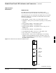
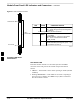
Module Status Indicators
Each of the non-passive plug-in modules has a bi-color (green & red)
LED status indicator located on the module front panel. The indicator is
labeled PWR/ALM. If both colors are turned on, the indicator is yellow.
Each plug-in module, except for the fan module, has its own alarm
(fault) detection circuitry that controls the state of the PWR/ALM LED.
The fan TACH signal of each fan module is monitored by the AMR.
Based on the status of this signal, the AMR controls the state of the
PWR/ALM LED on the fan module.
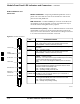
LED Status Combinations for
All Modules (except GLI2,
CSM, BBX2, MCC24, MCC8E)
PWR/ALM LED
The following list describes the states of the module status indicator.
Solid GREEN – module operating in a normal (fault free) condition.
Solid RED – module is operating in a fault (alarm) condition due to
electrical hardware failure.
Note that a fault (alarm) indication may or may not be due to a complete
module failure and normal service may or may not be reduced or
interrupted.
DC/DC Converter LED Status
Combinations
The PWR CNVTR has alarm (fault) detection circuitry that controls the
state of the PWR/ALM LED. This is true for both the C–CCP and LPA
power converters.
PWR/ALM LED
The following list describes the states of the bi-color LED.
Solid GREEN – module operating in a normal (fault free) condition.
Solid RED – module is operating in a fault (alarm) condition due to
electrical hardware problem.
6