
User's Manual

C–CCP Backplane Troubleshooting – continued
SC 4812T CDMA BTS Optimization/ATP
May 2000
6-18
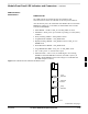
DC Power Problems
Perform the procedure in Table 6-22 to troubleshoot a DC input voltage
to power supply module failure.
Potentially lethal voltage and current levels are routed to
the BTS equipment. This test must be carried out with a
second person present, acting in a safety role. Remove all
rings, jewelry, and wrist watches prior to beginning this
test.
WARNING
No DC Input Voltage to Power Supply Module
Table 6-22: No DC Input Voltage to Power Supply Module
Step Action
1 Verify DC power is applied to the BTS frame.
2 Verify there are no breakers tripped.
* IMPORTANT
If a breaker has tripped, remove all modules from the applicable shelf supplied by the breaker and
attempt to reset it.
– If the breaker trips again, there is probably a cable or breaker problem within the frame.
– If the breaker does not trip, there is probably a defective module or sub–assembly within the shelf.
3 Verify that the C–CCP shelf breaker on the BTS frame breaker panel is functional.
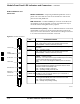
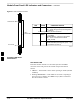
4 Use a voltmeter to determine if the input voltage is being routed to the C–CCP backplane by
measuring the DC voltage level on the PWR_IN cable.
– If the voltage is not present, there is probably a cable or breaker problem within the frame.
– If the voltage is present at the connector, reconnect and measure the level at the “VCC” power
feed clip on the distribution backplane. If the voltage is correct at the power clip, inspect the clip
for damage.
5 If everything appears to be correct, visually inspect the power supply module connectors.
6 Replace the power supply module with a known good module.
7 If steps 1 through 5 fail to indicate a problem, a C–CCP backplane failure (possibly an open trace) has
occurred.
6