
User's Manual

C–CCP Backplane Troubleshooting – continued
May 2000
6-15
SC 4812T CDMA BTS Optimization/ATP
Table 6-15 through Table 6-24 must be completed before
replacing ANY C–CCP backplane.
IMPORTANT
*
Digital Control Problems
No GLI2 Control via LMF (all GLI2s)
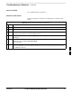
Follow the procedure in Table 6-15 to troubleshoot a GLI2 control via
LMF failure.
Table 6-15: No GLI2 Control via LMF (all GLI2s)
Step Action
1 Check the ethernet for proper connection, damage, shorts, or opens.
2 Verify the C–CCP backplane Shelf ID DIP switch is set correctly.
3 Visually check the master GLI2 connector (both board and backplane) for damage.
4 Replace the master GLI2 with a known good GLI2.
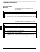
No GLI2 Control through Span Line Connection (All GLI2s)
Follow the procedures in Table 6-16 and Table 6-17 to troubleshoot
GLI2 control failures.
Table 6-16: No GLI2 Control through Span Line Connection (Both GLI2s)
Step Action
1 Verify the C–CCP backplane Shelf ID DIP switch is set correctly.
2 Verify that the BTS and GLI2s are correctly configured in the OMCR/CBSC data base.
3 Visually check the master GLI2 connector (both board and backplane) for damage.
4 Replace the master GLI2 with a known good GLI2.
5 Check the span line inputs from the top of the frame to the master GLI2 for proper connection and
damage.
6 Check the span line configuration on the MGLI2 (see Table 5-3 on page 5-3).
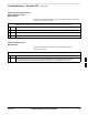
Table 6-17: MGLI2 Control Good – No Control over Co–located GLI2
Step Action
1 Verify that the BTS and GLI2s are correctly configured in the OMCR CBSC data base.
2 Check the ethernet for proper connection, damage, shorts, or opens.
3 Visually check all GLI2 connectors (both board and backplane) for damage.
4 Replace the remaining GLI2 with a known good GLI2.
6