
User's Manual

Prepare to Leave the Site – continued
SC 4812T CDMA BTS Optimization/ATP
May 2000
5-8
Re–connect BTS T1 Spans
and Integrated Frame Modem
Before leaving the site, connect any T1 span TELCO connectors that
were removed to allow the LMF to control the BTS. Refer to Table 5-8
and Figure 5-2 as required.
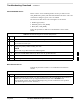
Table 5-8: T1/E1 Span/IFM Connections
Step Action
1 Connect the 50–pin TELCO cables to the BTS span I/O board 50–pin TELCO connectors.
2 If used, connect the dial–up modem RS–232 serial cable to the Site I/O board RS–232 9–pin
sub D connector.
* IMPORTANT
Verify that you connect both SPAN cables (if removed previously), and the Integrated Frame Modem
(IFM) “TELCO” connector.
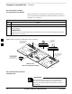
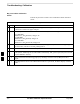
Figure 5-2: Site and Span I/O Boards T1 Span Connections
50–PIN TELCO
CONNECTORS
REMOVED
SPAN A CONNECTOR
(TELCO) INTERFACE
TO SPAN LINES
SPAN B CONNECTOR
(TELCO) INTERFACE
TO SPAN LINES
TOP OF frame
(Site I/O and Span I/O boards)
RS–232 9–PIN SUB D
CONNECTOR SERIAL
PORT FOR EXTERNAL
DIAL UP MODEM
CONNECTION (IF USED)
FW00299
Re–establish OMC–R Control/
Verifying T1/E1
After all activities at the site have been completed, and
after disconnecting the LMF, place a phone call to the
OMC–R and request the BTS be placed under control of
the OMC–R.
IMPORTANT
*
5