
User's Manual


BTS Alarms Testing – continued
SC 4812T CDMA BTS Optimization/ATP
May 2000
3-86
Table 3-46: CDI Alarm Input Verification Without the Alarms Test Box
Step Action
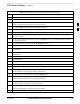
14 Refer to Figure 3-20 and sequentially short the ALARM A connector CDI 1 through CDI 18 pins
(25–26 through 59–60) together.
A clear alarm should be reported for each pair of pins that are shorted.
An alarm should be reported for each pair of pins when the short is removed.
15 Refer to Figure 3-20 and sequentially short the ALARM B connector CDI 19 through CDI 36 pins
(25–26 through 59–60) together.
A clear alarm should be reported for each pair of pins that are shorted.
An alarm should be reported for each pair of pins when the short is removed.
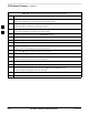
16 Select the MGLI.
17 Click on the Device menu
18 Click on the Customer Alarm Inputs menu item.
19 Click on Unequipped.
A status report window displays the results of the action.
20 Click on OK to close the status report window.
21 Refer to Figure 3-20 and sequentially short the ALARM A connector CDI 1 through CDI 18 pins
(25–26 through 59–60) together.
No alarms should be displayed.
22 Refer to Figure 3-20 and sequentially short the ALARM B connector CDI 19 through CDI 36 pins
(25–26 through 59–60) together.
No alarms should be displayed.
23 Load data to the MGLI to reset the alarm relay conditions according to the CDF file.
Pin and Signal Information for
Alarm Connectors
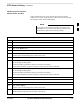
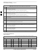
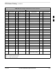
Table 3-47 lists the pins and signal names for Alarms A and B.
Table 3-47: Pin and Signal Information for Alarm Connectors
ALARM A ALARM B
Pin Signal Name Pin Signal Name Pin Signal Name Pin Signal Name
1 A CDO1 NC 31 Cust Retn 4 1 B CDO9 NC 31 B CDI 22
2 A CDO1 Com 32 A CDI 4 2 B CDO9 Com 32 Cust Retn 22
3 A CDO1 NO 33 Cust Retn 5 3 B CDO9 NO 33 B CDI 23
4 A CDO2 NC 34 A CDI 5 4 B CDO10 NC 34 Cust Retn 23
5 A CDO2 Com 35 Cust Retn 6 5 B CDO10 Com 35 B CDI 24
6 A CDO2 NO 36 A CDI 6 6 B CDO10 NO 36 Cust Retn 24
. . . continued on next page
3