
User's Manual


BTS Alarms Testing – continued
May 2000
3-83
SC 4812T CDMA BTS Optimization/ATP
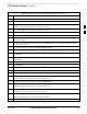
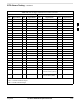
Table 3-45: CDI Alarm Input Verification Using the Alarms Test Box
Step Action
3 Click on the Device menu.
4 Click on the Customer Alarm Inputs menu item.
5 Click on N.O. Inputs.
A status report window displays the results of the action.
6 Click on the OK button to close the status report window.
7 Set all switches on the alarms test box to the Open position.
8 Connect the alarms test box to the ALARM A connector (see Figure 3-19).
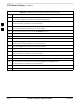
9 Set all of the switches on the alarms test box to the Closed position. An alarm should be reported for
each switch setting.
10 Set all of the switches on the alarms test box to the Open position. A clear alarm should be reported
for each switch setting.
11 Disconnect the alarms test box from the ALARM A connector.
12 Connect the alarms test box to the ALARM B connector.
13 Set all switches on the alarms test box to the Closed position. An alarm should be reported for each
switch setting
14 Set all switches on the alarms test box to the Open position. A clear alarm should be reported for each
switch setting.
15 Disconnect the alarms test box from the ALARM B connector.
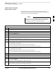
16 Select the MGLI.
17 Click on the Device menu.
18 Click on the Customer Alarm Inputs menu item.
19 Click on N.C. Inputs. A status report window displays the results of the action.
20 Click OK to close the status report window.
Alarms should be reported for alarm inputs 1 through 36.
21 Set all switches on the alarms test box to the Closed position.
22 Connect the alarms test box to the ALARM A connector.
Alarms should be reported for alarm inputs 1 through 18.
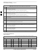
23 Set all switches on the alarms test box to the Open position.
An alarm should be reported for each switch setting.
24 Set all switches on the alarms test box to the Closed position.
A clear alarm should be reported for each switch setting.
25 Disconnect the alarms test box from the ALARM A connector.
. . . continued on next page
3