
User's Manual

BTS Alarms Testing – continued
SC 4812T CDMA BTS Optimization/ATP
May 2000
3-82
Abbreviations used in the following figures and tables are
defined as:
NC = normally closed
NO = normally open
COM or C = common
CDO = Customer Defined (Relay) Output
CDI = Customer Defined (Alarm) Input
NOTE
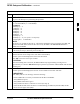
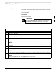
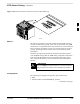
59 1
60 2
ALARM A
(AMR 1)
ALARM B
(AMR 2)
Returns
25
26
A CDI 18 . . . A CDI 1
59 1
60 2
Returns
25
26
B CDI 36 . . . B CDI 19
FW00302
Figure 3-20: AMR Connector Pin Numbering
The preferred method to verify alarms is to follow the
Alarms Test Box Procedure, Table 3-45. If not using an
Alarm Test Box, follow the procedure listed in Table 3-46.
NOTE
CDI Alarm Input Verification
with Alarms Test Box
Table 3-45 describes how to test the CDI alarm input verification using
the Alarm Test Box. Follow the steps as instructed and compare results
with the LMF display.
It may take a few seconds for alarms to be reported. The
default delay is 5 seconds. Leave the alarms test box
switches in the new position until the alarms have been
reported.
NOTE
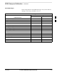
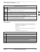
Table 3-45: CDI Alarm Input Verification Using the Alarms Test Box
Step Action
1 Connect the LMF to the BTS and log into the BTS.
2 Select the MGLI.
. . . continued on next page
3