
User's Manual

BTS Alarms Testing – continued
May 2000
3-81
SC 4812T CDMA BTS Optimization/ATP
ÂÂÂÂÂÂ
ÂÂÂÂÂÂ
ÂÂÂÂÂÂ
ÂÂÂÂÂÂ
ÂÂÂÂÂÂ
Á
Á
Á
Á
Á
Á
Á
Á
Á
59
1
60
2
59
1
60
2
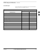
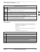
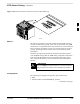
Figure 3-19: Alarm Connector Location and Connector Pin Numbering
FW00301
Purpose
The following procedures verify the customer defined alarms and relay
contacts are functioning properly. These tests are performed on all AMR
alarms/relays in a sequential manner until all have been verified. Perform
these procedures periodically to ensure the external alarms are reported
properly. Following these procedures ensures continued peak system
performance.
Study the site engineering documents and perform the following tests
only after first verifying that the AMR cabling configuration required to
interconnect the BTS frame with external alarm sensors and/or relays
meet requirements called out in the SC 4812T Series BTS Installation
Manual.
Motorola highly recommends that you read and understand
this procedure in its entirety before starting this procedure.
IMPORTANT
*
Test Equipment
The following test equipment is required to perform these tests:
LMF
Alarms Test Box (CGDSCMIS00014) –optional
. . . continued on next page
3