
User's Manual

Test Set Calibration – continued
May 2000
3-53
SC 4812T CDMA BTS Optimization/ATP
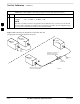
The short cable plus the TX cable configuration loss is measured –
The TX cable configuration normally consists of two coax cables with
type-N connectors and a directional coupler, a load, and an additional
attenuator (if required by the specified BTS). The total loss of the path
loss of the TX cable configuration must be as required for the BTS
(normally 30 or 50 dB).
Calibrating Cables with a
CDMA Analyzer
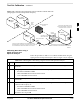
Cable Calibration is used to calibrate both TX and RX test cables.
Follow the procedure in Table 3-25 to calibrate the cables. Figure 3-10
illustrates the cable calibration test equipment setup. Appendix F covers
the procedures for manual cable calibration.
LMF cable calibration for PCS systems (1.7/1.9 GHz)
cannot be accomplished using an HP8921 analyzer with
PCS interface or an Advantest analyzer. A different
analyzer type or the signal generator and spectrum analyzer
method must be used (refer to Table 3-26 and Figure 3-17).
Cable calibration values are then manually entered.
NOTE
Prerequisites
Ensure the following prerequisites have been met before proceeding:
Test equipment to be calibrated has been connected correctly for cable
calibration.
Test equipment has been selected and calibrated.
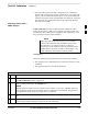
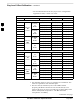
Table 3-25: Cable Calibration
Step Action
1 From the Util menu, select Cable Calibration.
A Cable Calibration window is displayed.
2 Enter a channel number(s) in the Channels box.
NOTE
Multiple channels numbers must be separated with a comma, no space (i.e., 200,800). When two
or more channels numbers are entered, the cables are calibrated for each channel. Interpolation is
accomplished for other channels as required for TX calibration.
3 Select TX and RX Cable Cal, TX Cable Cal, or RX Cable Cal in the Cable Calibration pick
list.
4 Click OK. Follow the direction displayed for each step.
A status report window displays the results of the cable calibration.
3