
User's Manual

Test Equipment Set–up – continued
SC 4812T CDMA BTS Optimization/ATP
May 2000
3-48
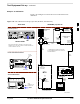
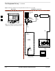
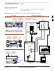
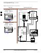
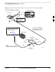
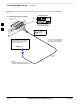
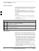
Figure 3-16: Typical RX ATP Setup with Directional Coupler (shown with or without RFDS)
RX RF FROM BTS
FRAME
3
4
1
2
5
6
Connect RX test cable between
the test set and the appropriate
RX antenna directional coupler.
RX ANTENNA DIRECTIONAL COUPLERS
RF FEED LINE TO
TX ANTENNA
REMOVED
COMMUNICATIONS
TEST SET
RFDS TX (RFM RX) COUPLER
OUTPUTS TO RFDS FWD(BTS)
ASU1 (SHADED) CONNECTORS
RX
(RFM TX)
TX
(RFM RX)
COBRA RFDS Detail
OUT
Appropriate test sets and the port
names for all model test sets are
described in Table 3-21.
RX Test
Cable
NOTE:
THIS SETUP APPLIES TO BOTH
STARTER AND EXPANSION FRAMES.
FW00115
3