
User's Manual

Test Equipment Set–up – continued
SC 4812T CDMA BTS Optimization/ATP
May 2000
3-40
Test Equipment Reference
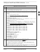
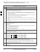
Chart
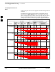
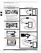
Table 3-21 depicts the current test equipment available meeting Motorola
standards.
To identify the connection ports, locate the test equipment presently
being used in the TEST SETS columns, and read down the column.
Where a ball appears in the column, connect one end of the test cable to
that port. Follow the horizontal line to locate the end connection(s),
reading up the column to identify the appropriate equipment/BTS port.
Table 3-21: Test Equipment Setup
TEST SETS ADDITIONAL TEST EQUIPMENT
SIGNAL
Cyber–
Test
Ad-
vantest
HP
8935
HP
8921A
HP
8921
W/PCS
Power
Meter
GPIB
Inter-
face LMF
Directional
Coupler & Pad*
BTS
EVEN SECOND
SYNCHRONIZATION
EVEN
SEC REF
EVEN SEC
SYNC IN
EVEN
SECOND
SYNC IN
EVEN
SECOND
SYNC IN
EVEN
SECOND
SYNC IN
19.6608 MHZ
CLOCK
TIME
BASE IN
CDMA
TIME BASE
IN
EXT
REF IN
CDMA
TIME BASE
IN
CDMA
TIME BASE
IN
CONTROL
IEEE 488 BUS
IEEE
488
GPIB HP–IB HP–IB GPIB
SERIAL
PORT
HP–IB HP–IB
TX TEST
CABLES
RF
IN/OUT
INPUT
50–OHM
RF
IN/OUT
TX1–6
RF
IN/OUT
RF
IN/OUT
20 DB
PAD
BTS
PORT
RX TEST
CABLES
RF GEN
OUT
RF OUT
50–OHM
DUPLEX RX1–6
DUPLEX
OUT
RF OUT
ONLY
SYNC
MONITOR
FREQ
MONITOR
3