
User's Manual
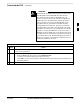
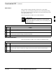

CSM System Time/GPS and LFR/HSO Verification – continued
May 2000
3-29
SC 4812T CDMA BTS Optimization/ATP
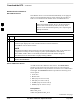
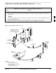
Low Frequency Receiver/
High Stability Oscillator
The CSM handles the overall configuration and status monitoring
functions of the LFR/HSO. In the event of GPS failure, the LFR/HSO is
capable of maintaining synchronization initially established by the GPS
reference signal.
The LFR requires an active external antenna to receive LORAN RF
signals. Timing pulses are derived from this signal, which is
synchronized to Universal Time Coordinates (UTC) and GPS time. The
LFR can maintain system time indefinitely after initial GPS lock.
The HSO is a high stability 10 MHz oscillator with the necessary
interface to the CSMs. The HSO is typically installed in those
geographical areas not covered by the LORAN–C system. Since the
HSO is a free–standing oscillator, system time can only be maintained
for 24 hours after 24 hours of GPS lock.
Upgrades and Expansions: LFR2/HSO2/HSOX
LFR2/HSO2 (second generation cards) both export a timing signal to the
expansion or logical BTS frames. The associated expansion or logical
frames require an HSO–expansion (HSOX) whether the starter frame has
an LFR2 or an HSO2. The HSOX accepts input from the starter frame
and interfaces with the CSM cards in the expansion frame. LFR and
LFR2 use the same source code in source selection (see Table 3-17).
HSO, HSO2, and HSOX use the same source code in source selection
(see Table 3-17).
Allow the base site and test equipment to warm up for
60 minutes after any interruption in oscillator power. CSM
board warm-up allows the oscillator oven temperature and
oscillator frequency to stabilize prior to test. Test
equipment warm-up allows the Rubidium standard
timebase to stabilize in frequency before any measurements
are made.
NOTE
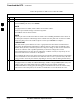
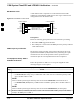
Front Panel LEDs
The status of the LEDs on the CSM boards are as follows:
Steady Green – Master CSM locked to GPS or LFR (INS).
Rapidly Flashing Green – Standby CSM locked to GPS or LFR
(STBY).
Flashing Green/Rapidly Flashing Red – CSM OOS–RAM attempting
to lock on GPS signal.
Rapidly Flashing Green and Red – Alarm condition exists. Trouble
Notifications (TNs) are currently being reported to the GLI.
3