
User's Manual

CSM System Time/GPS and LFR/HSO Verification
SC 4812T CDMA BTS Optimization/ATP
May 2000
3-28
CSM & LFR Background
The primary function of the Clock Synchronization Manager (CSM)
boards (slots 1 and 2) is to maintain CDMA system time. The CSM in
slot 1 is the primary timing source while slot 2 provides redundancy. The
CSM2 card (CSM second generation) is required when using the remote
GPS receiver (R–GPS). R–GPS uses a GPS receiver in the antenna head
that has a digital output to the CSM2 card. CSM2 can have a daughter
card as a local GPS receiver to support an RF–GPS signal.
The CSM2 switches between the primary and redundant units (slots 1
and 2) upon failure or command. CDMA Clock Distribution
Cards (CCDs) buffer and distribute even–second reference and 19.6608
MHz clocks. CCD 1 is married to CSM 1 and CCD 2 is married to
CSM 2. A failure on CSM 1 or CCD 1 cause the system to switch to
redundant CSM 2 and CCD 2.
In a typical operation, the primary CSM locks its Digital Phase Locked
Loop (DPLL) circuits to GPS signals. These signals are generated by
either an on–board GPS module (RF–GPS) or a remote GPS receiver
(R–GPS). The CSM2 card is required when using the R–GPS. DPLL
circuits employed by the CSM provide switching between the primary
and redundant unit upon request. Synchronization between the primary
and redundant CSM cards, as well as the LFR or HSO back–up source,
provides excellent reliability and performance.
Each CSM board features an ovenized, crystal oscillator that provides
19.6608 MHz clock, even second tick reference, and 3 MHz sinewave
reference, referenced to the selected synchronization source (GPS,
LORAN–C Frequency Receiver (LFR), or High Stability Oscillator
(HSO), T1 Span, or external reference oscillator sources). The 3 MHz
signals are also routed to the RDM EXP 1A & 1B connectors on the top
interconnect panel for distribution to co–located frames at the site.
Fault management has the capability of switching between the GPS
synchronization source and the LFR/HSO backup source in the event of
a GPS receiver failure on CSM 1. During normal operation, the CSM 1
board selects GPS as the primary source (see Table 3-18). The source
selection can also be overridden via the LMF or by the system software.
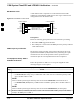
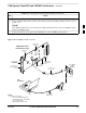
All boards are mounted in the C–CCP shelf at the top of the BTS frame.
Figure 3-9 on page 3-31 illustrates the location of the boards in the BTS
frame. The diagram also shows the CSM front panel.
3