
User's Manual

Download the BTS – continued
May 2000
3-25
SC 4812T CDMA BTS Optimization/ATP
Follow the procedure in Table 3-13 to select a CSM Clock Source.
Table 3-13: Select CSM Clock Source
Step Action
1 Select the applicable CSM(s).
2 Click on the Device menu.
3 Click on the Clock Source menu item.
4 Click on the Select menu item.
A clock source selection window is displayed.
5 Select the applicable clock source in the Clock Reference Source pick lists.
Uncheck the related check box if you do not want the displayed pick list item to be used.
6 Click on the OK button.
A status report window displays the results of the selection action.
7 Click on the OK button to close the status report window.
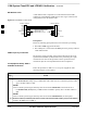
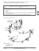
Enable CSMs
Each BTS CSM system features two CSM boards per site. In a typical
operation, the primary CSM locks its Digital Phase Locked Loop
(DPLL) circuits to GPS signals. These signals are generated by either an
on–board GPS module (RF–GPS) or a remote GPS receiver (R–GPS).
The CSM2 card is required when using the R–GPS. The GPS receiver
(mounted on CSM 1) is the primary timing reference and synchronizes
the entire cellular system. CSM 2 provides redundancy but does not have
a GPS receiver.
The BTS may be equipped with a remote GPS, LORAN–C Low
Frequency Receiver (LFR), or HSO 10 MHz Rubidium source, which
the CSM can use as a secondary timing reference. In all cases, the CSM
monitors and determines what reference to use at a given time.
– CSMs are code loaded at the factory. This data is
retained in EEPROM. The download code procedure
is required in the event it becomes necessary to code
load CSMs with updated software versions. Use the
status function to determine the current code load
versions.
– For n0n–RGPS sites only, verify the CSM configured
with the GPS receiver “daughter board” is installed in
the CSM–1 slot before continuing.
– The CSM(s) and MCC(s) to be enabled must have
been downloaded with code (Yellow, OOS–RAM)
and data.
IMPORTANT
*
. . . continued on next page
3