
User Manual

7-75
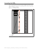
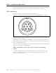
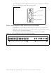
Power supply cable connections
Table 7.3 describes the pins of the power cable used with the RMB.
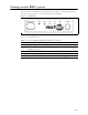
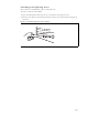
Diagnostic cable connections
It is recommended that you use the diagnostic cable provided by NextNet Wireless to
configure the RMBs. One end of the cable has a RJ-45 type connector.
Table 7.4 describes the cable’s pins.
Table 7.3 Power cable pins
Pin number
American wire
gauge (AWG) Color
Pin 1 18 AWG Black
Pin 2 18 AWG Black
Pin 3
Pin 4 18 AWG Black
Pin 5 18 AWG Black
Pin 6
Pin 7 18 AWG Black
Pin 8 18 AWG Black
Pin 9 22 AWG White
Pin 10 22 AWG Green
Pin 11 18 AWG Red
Pin 12 18 AWG Red
Pin 13
Pin 14 18 AWG Red
Pin 15 18 AWG Red
Pin 16
Pin 17 18 AWG Red
Pin 18 18 AWG Red
Table 7.4 Diagnostic cable pin connections (RJ-45)
Pin number, color Connection
1 no connection
2 no connection
3 no connection
4, red GND
5, green RXD
6, yellow TXD
7 no connection
8 no connection
9 no connection