
User Manual

7-73
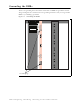
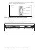
Turning on the RMB’s power
The front panel of the RMB has a programming cable connection, 5 light-emitting diodes,
and a power button. Figure 7.6 shows the front panel of the RMB.
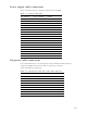
To turn on the RMB, press the power button. The LEDs then light. Table 7.2 describes what
the base station LEDs indicate.
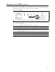
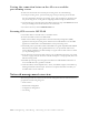
Figure 7.6 RMB LEDs
Table 7.2 Description of LEDs on the base station
LED Description
1 (PWR) When this green LED is lit, the RMB has power.
2 (NET) When this yellow LED is lit and blinking, information is being received on the
RMB’s Ethernet port.
3 (PPS) The LED indicates that the RMB is receiving the 1 pulse per second signal.
4 (AIR) When this LED is lit, the airlink on the RMB is operating.
5 (ALM) When this red LED is lit, an alarm on the RMB has been triggered.
POWERALMAIRPPSNETPWRDIAGNOSTICS