
User Manual

6-54 Configuring, Installing, and Using Carrier Infrastructure
TVS module connectors
The TVS module has connectors on both its right and left sides.
Base station to TVS connector
The base station connector supplies power and an Ethernet connection to the base station.
Connect cable 597-6027-0xxx to this side of the TVS module.
Note: Use the AUX +48 VDC and AUX ETHERNET connections only if you need to cut
off the circular connector from the power/Ethernet cable (597-6013-0xxx). For example, you
might not be able to use the circular connector if it cannot fit through a space or hole in a wall
at the installation site. Instead, you may split the cable and put a 4 position .150" spaced
terminal block on the Ethernet wires, and a 4 position .200" spaced terminal block on the
power wires. Then, you will plug the appropriate connector from the split cable into the
corresponding connector in the TVS module. Table 6.3, “Function of wires in cable 597-
6027-0xxx” on page 6-53 describes the wires in the cable.
Power supply cable and ISP Ethernet network connector
The other side of the module has a connector for both an Ethernet cable coming from your
ISP network and for the +48 VDC power coming from a power supply.
Note: To ensure your base station is properly protected from possible lightning strikes,
ensure you plug the power cable coming from your power supply into this connector in the
TVS module. If you plug the power cable into the base station connector side, the base
station will power up, but you will not be properly protected against possible lightning strikes.
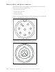
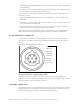
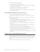
Figure 6.5 TVS module connector: Base station connector
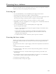
Figure 6.6 TVS module connector: power/Ethernet connector
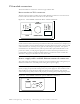
+48 VDC ETHERNET
BASE
CONNECTION
+ (RED)
+ (RED/WT)
-(BLK/WT)
-(BLK)
TX+(OG/WT)
TX-(ORG)
RX+(GR/WT)
RX-(GRN)
POWER/ETHERNET
+48 VDC
5AMP
POWER
ISP
ETHERNET
+-