
User Manual

6-52 Configuring, Installing, and Using Carrier Infrastructure
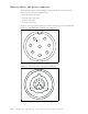
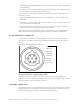
Ethernet (data) and power connector
The Ethernet and power connector supplies data and DC power to the base station.
The connector to the TVS module has 8 pins:
• Ethernet transmit uses 2 pins.
• Ethernet receive uses 2 pins.
• Power V- uses 2 pins.
• Power V+ uses 2 pins.
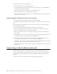
Figure 6.3 shows the Ethernet and power connector which plugs into the TVS module.
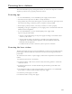
The connector to the base station has 13 pins.
Figure 6.3 Ethernet (data) and power connector
Figure 6.4 Ethernet (data) and power connector
8
1
2
3
4
5
6
7
1
2
3
4
5
6
7
8
9
10
11
12
13