
User Manual

1-4 Configuring, Installing, and Using Carrier Infrastructure
Head-end switch, base station cell switch, and ISP switch
overview
The network access provider must supply switches for their network, which include the head-
end switch and the switches used at the base station cell site. The network access provider
must also assist their ISPs when the ISPs program their switches with the proper ISP VLAN
IDs.
The base stations are grouped together into cells, with between 1 and 6 base stations at a cell
site. (If the network access provider chooses to stack base stations, more than 6 base stations
can exist in a cell.) To form the base station LAN, the base stations are connected to a switch
at the cell site.
WAN links are then used to connect the cell sites to the head end switch. The head end
switch splits incoming traffic to the management VLAN and to the appropriate ISP VLAN.
The ISP then has a configured switch that controls traffic coming into and out of the ISP
VLANs.
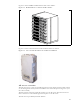
Installation overview
This section provides a high-level overview of how to install the indoor, rackmount base
station (RMB), as well as the base transciever stations (BTS) that can be installed outdoors or
indoors.
Installation steps common to RMB and BTS
1 Plan the installation of base stations:
a Choose an appropriate location for the base station installation. For more information,
refer to the section “Choosing an installation location” on page 1-6 in this chapter.
b Design the deployment of base stations. Determine how base stations will be deployed
by marking a location on a map that shows where each base station will be installed.
Also determine naming conventions for cells, sectors, zones, and base stations names.
For more information, refer to the section, “Designing the deployment of base
stations” on page 1-9.
2 Plan for system components that you need to supply to complete the network. For more
information, refer to the section “Assessing network access provider equipment needs” on
page 1-7 in this chapter.
3 Install and configure the access provider (AP) server. For more information, refer to
Chapter 3, “Installing the AP server,” in this guide.
4 On the AP server, configure zone names, VLAN IDs, and the ISP IDs. For more
information, refer to Chapter 3, “Installing the AP server,” in this guide.
5 Using the NextNet Operating System (NNOS), configure the base stations before
deploying them in the field. For more information, refer to the chapter “Configuring base
stations” in this guide.
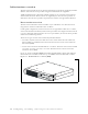
RMB installation overview
This section provides a high-level overview of how to install the base station cabinet onto a
19 inch rack, and then how to install the base stations into the cabinet.
1 Slide the metal base station cabinet into the 19 inch rack.
2 Install the power supply onto the 19 inch rack.