
User Manual
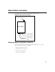
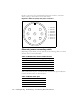
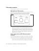
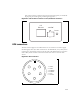
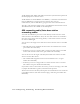
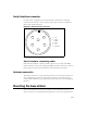
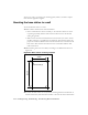
Table Of Contents
- Preface Overview
- About this guide
- Additional documentation
- Typographical conventions this guide uses
- Where to go for more help
- Chapter overview
- System overview
- Installation overview
- Planning the installation
- Chapter overview
- Before you begin
- Using Term or Telnet to help configure base stations
- Setting base station configuration parameters
- Chapter overview
- Before you begin
- Cell wiring
- Base station connectors
- Mounting the base station
- Connecting the antenna to the base station
- Connecting the GPS equipment to a base station
- Connecting to the backbone network
- Powering base stations
- Verifying system operation
- Appendix overview
- Appendix overview

3-21
Serial interface connector
For base station configuration, the serial interface connector lets you directly
connect the base station to a PC or laptop. The six-pin connector is an RS-232
cable (10 ft), physical interface.
Note: “nu” indicates that the pin is not used.
Serial interface connecting cable
Cable 597-6014-0010 has a female, circular connector on one end, and a DB-9
female connector on the other end. Plug the DB-9 end of the cable into your PC or
laptop. Plug the other end of the cable into the serial interface connector.
Antenna connector
The antenna connector is a type N female connector. It has a built-in, internal 1/4
wave stub lightning protector. Connect the base station to the antenna using a
coaxial cable. Connect the proper lightning ground wiring to the antenna lightning
protector.
Mounting the base station
You can mount the base station to any surface. To mount the base station to a
wall, you need to use the supplied mounting brackets. If you are installing the base
Figure 3.7
Serial interface connector
51
3
2 4
1 - nu
2 - TxD
3 - RxD
4 - TxD
5 - nu
6 - Ground
6