
User Manual
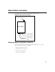
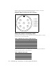
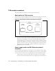
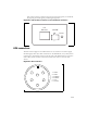
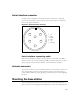
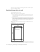
Table Of Contents
- Preface Overview
- About this guide
- Additional documentation
- Typographical conventions this guide uses
- Where to go for more help
- Chapter overview
- System overview
- Installation overview
- Planning the installation
- Chapter overview
- Before you begin
- Using Term or Telnet to help configure base stations
- Setting base station configuration parameters
- Chapter overview
- Before you begin
- Cell wiring
- Base station connectors
- Mounting the base station
- Connecting the antenna to the base station
- Connecting the GPS equipment to a base station
- Connecting to the backbone network
- Powering base stations
- Verifying system operation
- Appendix overview
- Appendix overview

3-18 Configuring, Installing, and Using Base Stations
TVS module connectors
The TVS module has connectors on both its right and left sides.
Base station to TVS connector
The base station connector supplies power and an Ethernet connection to the base
station. Connect cable 597-6013-0xxx to this side of the TVS module.
Note: Use the AUX +48 VDC and AUX ETHERNET connections only if you
need to cut off the circular connector from the power/Ethernet cable (597-
6013-0xxx). For example, if you need to route the cable through a wall at
your installation site, you will not use the circular connector. Instead, you will
split the cable and put a 6-pin, RJ-11 connector on some wires, and a power
connector on others. Then, you will plug the appropriate connector from the
split cable into the corresponding connector in the TVS module. Table 3.3
describes the wires in the cable.
Power supply cable and ISP Ethernet network
connector
The other side of the module has a connector for both an Ethernet cable coming
from your ISP network and for the +48 VDC power coming from a power supply.
Note: To ensure your base station is properly protected from possible lightning
strikes, ensure you plug the power cable coming from your power supply
into this connector in the TVS module. If you plug the power cable into the
Figure 3.4
TVS module connector: Base station connector
POWER / ETHERNET
AUX
+48 VDC
Base
Connection
AUX
ETHERNET
+ -