
User Manual
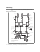
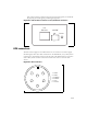
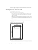
Table Of Contents
- Preface Overview
- About this guide
- Additional documentation
- Typographical conventions this guide uses
- Where to go for more help
- Chapter overview
- System overview
- Installation overview
- Planning the installation
- Chapter overview
- Before you begin
- Using Term or Telnet to help configure base stations
- Setting base station configuration parameters
- Chapter overview
- Before you begin
- Cell wiring
- Base station connectors
- Mounting the base station
- Connecting the antenna to the base station
- Connecting the GPS equipment to a base station
- Connecting to the backbone network
- Powering base stations
- Verifying system operation
- Appendix overview
- Appendix overview

3-14 Configuring, Installing, and Using Base Stations
Cell wiring
Figure 3.1 shows how a cell, base stations, and ancillary equipment are wired
together.
Figure 3.1
Cell wiring diagram
1 2 6
Panel
Antenna*
Coax jumper*
Coax - main
feed*
Coax jumper*
GPS Unit
GPS
Interface
Cable
TVS
Module
Backbone swtich* P ower s upply*
UPS*
AC power cord*
DC power cable*
In-line or
panel fuse*
Base station
*Not provided as component of
standard NextNet Wireless base
station product
GPS inter-base
station cable
E thernet/power
cable
Load
Termination
Optional S erial
C onnection and
Laptop Compute
r
Backbone
connection cable*
E thernet cable*