System Requirements for Installation and Operation D N 00283911 Issue 2 D R A F T 1 -en © N okia Corporat ion N okia P ropriet ary and Confident ial 1 (43)
S y st em R equirem ent s forInst al l at ion and O perat ion The inform at ion int his docum entis subj ectt o change w it houtnot ice and describes onl y t he productdefined int he int roduct ion of t his docum ent at ion.
FCC §15.105 - Information to user -This equipm enthas been t est ed and found t o com pl y w it ht he l im it s fora Cl ass B digit aldevice,pursuantt o part15 of t he F CC R ul es.These l im it s are designed t o provide reasonabl e prot ect ion against harm fulint erference ina resident ialinst al l at ion.
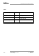
S y st em R equirem ent s forInst al l at ion and O perat ion History Date Version Author Details 26-10-2000 D raft1 T N W il l iam s Com pil at ion of a firstdraft 08 -01 -2001 D raft2 IndiL iepa R evised based on feedback from subj ect m at t erex pert . 26 -01 -2001 Issue 1 IndiL iepa R evised aft ervisitt o Tekm arby H arriand review by M arc P aul l .
A boutt his docum ent 1 About this document This document introduces the requirements set by Nokia for successful installation and operation. Use this document as the source for the following information needed in the planning of installation: • Specification on the environmental conditions during transportation, storage and operation • Space requirements and other site-related installation matters • Site grounding and power supply • Interface connections • Installation tools.
S y st em R equirem ent s forInst al l at ion and O perat ion 6 (43) © N okia Corporat ion N okia P ropriet ary and Confident ial D N 00283911 Issue 2 D R A F T 1 -en
Inst al l at ion sit e requirem ent s 2 Installation site requirements Prior to installation of the Nokia InLite system, it is most important that certain actions have been carried out to ensure installation continuity and safety. 2.1 Checking the site A number of aspects need to be verified as being satisfactory. Accessibility Check the following: • Site safety access is provided • The site is accessible to installation, commissioning and maintenance personnel.
S y st em R equirem ent s forInst al l at ion and O perat ion • A distance of two meters must be maintained between the MU or RUs (RUs) and a heating opening. • The RUs should be mounted in reasonable locations. • The RUs should not be installed inside heating or conditioning systems. • The RUs should not be installed inside a cable pipeline. • Bear in mind that the temperature in the upper part of a room is higher than at eye level.
Inst al l at ion sit e requirem ent s 2.2 Checking the site environment Check that the following requirements are satisfactory at the site: D N 00283911 Issue 2 D R A F T 1 -en • The site storage, transportation and operation of the Nokia InLite must conform with the various international and national environmental standards for temperature, humidity, EMC and noise.
S y st em R equirem ent s forInst al l at ion and O perat ion 10 (43) © N okia Corporat ion N okia P ropriet ary and Confident ial D N 00283911 Issue 2 D R A F T 1 -en
E nvironm ent 3 Environment This chapter defines the classes of environmental conditions and their severities to which the Nokia InLite can be exposed. The information is organised in the following parts: 3.1 • Conditions for Storage • Conditions for Transportation • Conditions for Operation Storage This section defines the environmental conditions, to which the Nokia InLite can be exposed during storage. Caut ion The Nokia InLite must be stored in its original package before the installation.
S y st em R equirem ent s forInst al l at ion and O perat ion Environmental parameter L ow rel at ive hum idit y 10% H igh rel at ive hum idit y 100% L ow absol ut e hum idit y 0.5 g/m 3 H igh absol ut e hum idit y 29 g/m 3 R ainint ensit y none Tem perat ure change rat e (average of 5 m inut es) 0.5 °C/m in. 0.9 °F /m in. L ow airpressure 70 kP a 10.15 psi H igh airpressure 106 kP a 15.
E nvironm ent 3.2 Transportation This section defines the environmental conditions which the Nokia InLite can be exposed to during transportation. Caut ion The Nokia InLite must be transported in its original package before the installation. N ot e The Nokia InLite is delivered to the customer with some of the plug-in units preinstalled (Control Unit, Power Supply Unit/s, Switch Matrix/Dual Band RF unit). 3.2.1 ETSI standard for transportation The Nokia InLite is Class 2.
S y st em R equirem ent s forInst al l at ion and O perat ion Environmental parameter Value Tem perat ure change air/w at er +40/+5 °C +104/+41 °F R el at ive hum idit y ,notcom bined w it h rapid t em perat ure changes 95% 95% +40 °C 104 °F R el at ive hum idit y ,com bined w it h rapid t em perat ure changes air/air,athigh rel at ive hum idit y 95% 95% -40 °C /+30 °C -40 °F /+86 °F A bsol ut e hum idit y ,com bined w it h rapid 60 g/m 3 +70/+15 °C t em perat ure changes air/air,athigh w at erco
E nvironm ent 3.3 Operation This section defines the environmental conditions during the operation of the Nokia InLite at locations which are not protected from direct weather influences. N ot e When surveying the prospective sites, consider the values presented in this section. Operating conditions are defined as stationary: the equipment is mounted on a structure, or on a mounting device, or it is permanently placed at a certain site. The Nokia InLite is not intended for portable use. 3.3.
S y st em R equirem ent s forInst al l at ion and O perat ion Environmental parameter S ol arradiat ion 700 W /m 2 H eatradiat ion insignificant S urrounding airm ovem ent 5m /s 164 ft ./s Condit ions of condensat ion Yes Condit ions of precipit at ion (rain,snow ,hailet c.) No L ow raint em perat ure N otappl icabl e. Condit ions of w at erfrom sources ot hert han rain N otappl icabl e. Condit ions of icing and frost ing No Tabl e 3. 3.3.
E nvironm ent Scheme Group and National Deviations as detailed in CB Bulletin 96A March 2000. D N 00283911 Issue 2 D R A F T 1 -en • UL 3rd Ed. • CSA C22.
S y st em R equirem ent s forInst al l at ion and O perat ion 18 (43) © N okia Corporat ion N okia P ropriet ary and Confident ial D N 00283911 Issue 2 D R A F T 1 -en
Inst al l at ion requirem ent s 4 Installation requirements This chapter specifies the preparatory requirements for the installation of the Nokia InLite system. 4.1 Checking the site Before the Nokia InLite can be installed, the site must be properly surveyed and prepared, and all the required external services must be correctly installed. The site survey must identify any special requirements for the installation. The site must meet the following requirements before the installation can begin: 4.2 1.
S y st em R equirem ent s forInst al l at ion and O perat ion 840m m (33.1) 114m m (4.5) 310m m (12.2) 215m m (8.5) N O TE : D im ensions inm m (inch) F igure 1. D im ensions of N okia InL it e M ainU nit The MU weighs approximately 16.5 kg (36 lb.). The mounting frame weighs approximately 2 kg (4.4 lb.). 4.2.1.2 Remote Unit and mounting rack, enclosure class IP41 The dimensions of the RU are shown in Figure .
Inst al l at ion requirem ent s 37 (1.46) 240 (9.45) 222 (8.74) N O TE : D im ensionsinm m (inch) F igure 2. D im ensions of t he R em ot e U nit The RU weighs 1.7 kg (3.8lb).
S y st em R equirem ent s forInst al l at ion and O perat ion 240 (9.45) 280 (11.02) 55 (2.17) F igure 3. 4.2.1.3 D im ensions of t he R U m ount ing rack (show n w it h R U m ount ed) Remote Unit, enclosure class IP53 The dimensions of the RU are shown in Figure .
Inst al l at ion requirem ent s F igure 4. D im ensions of t he R em ot e U nit The RU weighs 2.5 kg (5.5lb). 4.2.1.4 Remote Unit, enclosure class IP64 The dimensions of the RU are shown in Figure .
S y st em R equirem ent s forInst al l at ion and O perat ion F igure 5. D im ensions of t he R em ot e U nit The RU weighs 11 kg (24.25lb). 4.2.2 Clearances around the Main Unit and Remote Units 4.2.2.1 Main Unit The required clearances around the MU are shown in Figure .
Inst al l at ion requirem ent s Top view F rontview 100 (3.94) 400 (15.74) 200 (7.88) 114 (4.5) 400 (15.74) 840 (33.1) 1454 (57.28) 100 (3.94) 310 (12.2) F igure 6. 4.2.2.
S y st em R equirem ent s forInst al l at ion and O perat ion 100 (3.94) 50 (1.97) 50 (1.97) 400 (15.7) N ot e: D im ensions in m m (inch) F igure 7. Cl earances around t he R em ot e U nitIP 41 The clearances are required for: • Lifting the unit from the rack • Fibre optic cables, antenna cables and power cables. The required clearances arond the IP53 RU are shown in Figure XX.
Inst al l at ion requirem ent s F igure 8. Cl earances around t he R em ot e U nitIP 53 The required clearances arond the IP64 RU are shown in Figure XX.
S y st em R equirem ent s forInst al l at ion and O perat ion F igure 9. Cl earances around t he R em ot e U nitIP 64 4.3 Mounting locations and positions 4.3.1 Main Unit The MU can only be installed at indoor locations and should be mounted vertically on a wall, pole or other vertical support.
Inst al l at ion requirem ent s F igure 10. M ount ing posit ion of N okia InL it e M ainU nit 4.3.2 RU and mounting rack The RU can be mounted on a wall, pole or other vertical support. The RU and mounting rack are mounted vertically. N ot e The RU and mounting rack should never be installed on a ceiling. A local AC power socket must be provided at the installation location or alternatively, a centralised DC power supply may be used.
S y st em R equirem ent s forInst al l at ion and O perat ion 4.4 Requirements for wall and pole installation Qualified personnel must inspect the installation wall and/or pole or other vertical support before mounting the MU, RU and mounting rack. The installation wall or pole must be strong enough to bear the weight of each unit. The optional pole mounting kit can be used when the installation pole diameter is between 60 and 300 mm (2.36 and 11.81 in). These dimensions are applicable to the MU.
Inst al l at ion requirem ent s • The routing of the ground cable must be as direct as possible. Unnecessary loops should be avoided. N ot e A grounding cable can be ordered from Nokia. 4.6 Mains power WARNING Follow the national legislation when working with the power supply. It is advisable that the socket used for the MU and RUs are permanently wired in accordance with current local and national wiring standards. All ground connections must be secure and non-removable.
S y st em R equirem ent s forInst al l at ion and O perat ion 4.6.3 • 220 VAC • -48 VDC Power consumption The power consumption of the MU is dependent on the RU configuration.The consumption of the MU is less than 100 W. The power consumption of one RU is 15 W. 4.6.4 Connectors, cables and fuses for cable protection N ot e A prefabricated mains power cable for the RU is supplied by Nokia.
Inst al l at ion requirem ent s Tabl e 5. Connect ors,cabl es and recom m ended fuses N ot e In general, the fuses for cable protection have to be rated according to the national electrical safety regulations. 4.7 Painting the Main Unit cover If desired, the MU cover can be painted to make it better blend into the surrounding environment. Some dark colours with higher absorptivity may be restricted.
S y st em R equirem ent s forInst al l at ion and O perat ion F igure 11. R em oving t he covert op 34 (43) 3. Remove stains and dust from the surface of the cover with an alcoholic or acidic wash, or wipe it clean with a piece of cloth moistened with water and mild washing agent. Do not use washing agents that contain alkalis, aromatic, chlorinated, or fluorinated hydrocarbons, esters or ketones. 4. Rinse with water to remove any residue of cleaning chemicals. 5.
Inst al l at ion requirem ent s F igure 12. A reas used forhol ding t he cabl e coverpart s during paint ing 8. Spray paint over the outside surface of the cover. Spraying should be done at room temperature with relative air humidity of 50-65%. N ot e The maximum thickness of the paint should not exceed 100 µm. 9. Dry the parts either in an oven or let the paint dry at room temperature according to the paint manufacturer’s drying instructions.
S y st em R equirem ent s forInst al l at ion and O perat ion 36 (43) © N okia Corporat ion N okia P ropriet ary and Confident ial D N 00283911 Issue 2 D R A F T 1 -en
Int erfaces and cabl es 5 Interfaces and cables This chapter describes the external interfaces and interconnecting cables (excluding the grounding and power supply cables) for the Nokia InLite. N ot e The following cables can be ordered from Nokia.
S y st em R equirem ent s forInst al l at ion and O perat ion Tabl e 6. 5.1.1 Connect ors of t he M ainU nit Local Unit Figure shows the layout of the fibre optical connectors. RX 1 RX 2 RX 3 RX 4 TX 1 TX 2 TX 3 TX 4 F igure 13. F ibre opt icalconnect ors of t he L ocalU nit Interface connector O pt icalTX or RX Tabl e 7. 5.
Int erfaces and cabl es Interface connector Connector type Cable type/diameter O pt icalTX or RX 2 S C /A P C (fem al e) 125 µm singl e m ode E xt ernal al arm 2 M ol ex (fem al e) - Tabl e 8.
S y st em R equirem ent s forInst al l at ion and O perat ion 40 (43) © N okia Corporat ion N okia P ropriet ary and Confident ial D N 00283911 Issue 2 D R A F T 1 -en
Inst al l at ion equipm ent 6 Installation equipment This section specifies the equipment that is recommended for the installation of the Nokia InLite, but not included in the Nokia InLite delivery. The recommended tools are: Tool Used for Torque driver,T10 Torx bitw it h m in.60 m m shaft U nitret aining screw s D N 00283911 Issue 2 D R A F T 1 -en Torque driver,4 m m A l l en bitw it h m in.60 m m shaft M U m ount ing screw s (5.5 N m /4.06 ft -l b.) G round cabl e fix ing (5.5 N m /4.06 ft -l b.
S y st em R equirem ent s forInst al l at ion and O perat ion Tabl e 9. R ecom m ended t ool s and usage Additional tools/equipment include: • 2 x radio phones for communicating when testing the fibre optic cable splicing • Spirit level for checking the horizontal level of the MU and RU • Tape measure • Hammer • Screwdrivers • Crimping tool for assembling the power supply cable connector N ot e A set of tools needed for assembling the cable connectors is available from Nokia.
Inst al l at ion equipm ent Torque driver(0-6 N m /0-5 ft -l b) Torque socketspanner/w rench (5-20 N m /3-14 ft -lb) Torque key S ide-cut t ing pl iers F igure 14.