Maintenance D N 00283717 Issue 2 D R A F T 1 -en © N okia Corporat ion N okia P ropriet ary and Confident ial 1 (26)
M aint enance The inform at ion int his docum entis subj ectt o change w it houtnot ice and describes onl y t he productdefined int he int roduct ion of t his docum ent at ion.This docum entis int ended fort he use of N okia N et w orks'cust om ers onl y fort he purposes of t he agreem entunderw hich t he docum entis subm it t ed,and no partof itm ay be reproduced ort ransm it t ed in any form orm eans w it houtt he priorw rit t en perm ission of N okia N et w orks.
FCC §15.105 - Information to user -This equipm enthas been t est ed and found t o com pl y w it ht he l im it s fora Cl ass B digit aldevice,pursuantt o part15 of t he F CC R ul es.These l im it s are designed t o provide reasonabl e prot ect ion against harm fulint erference ina resident ialinst al l at ion.
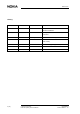
M aint enance History Date Version Author Details 22-5-2000 D raft 1 N .T.Thom as Com pil at ion of a firstdraftof t he U ser M anual : inst al l at ion 13-10-2000 D raft2 T N W il l iam s D raftupdat ed t o incl ude R F t eam com m ent s.
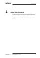
A boutt his docum ent 1 About this document This document provides instructions for maintaining the InLite. Maintenance procedures are carried out to ensure the efficient operation of the Nokia InLite system after it has been installed and commissioned. Throughout the document, warnings, cautions and notes are given whenever appropriate.
M aint enance 6 (26) © N okia Corporat ion N okia P ropriet ary and Confident ial D N 00283717 Issue 2 D R A F T 1 -en
P revent ive m aint enance 2 Preventive maintenance The Nokia InLite system requires a minimum of maintenance and supervision. Should an alarm condition occur, its location can readily be determined, using the laptop PC, then quickly corrected. To ensure the continued integrity of the InLite system, certain maintenance tasks must be performed at regular periods. 2.1 Periodic checks Visual inspection and cleaning Check that the following conditions are satisfied: 2.2 1.
M aint enance Consult with the indoor network planners and use the Switch Matrix capability to reroute services and capacity to other MUs or RUs to reduce or avoid cut in services or in RF coverage. Pay attention to the fact that Intelligent Network dedicated services (e.g., GSM Office, Private Virtual Network) located in a specific area of a building cannot be relocated.
R epair 3 Repair 3.1 Locating faults Faults in the MU or the Remote Unit can be diagnosed and located using the Supervisor software application installed on the laptop PC. WARNING All persons who perform operations on this equipment should be advised of the potential dangers. Warnings and cautions are provided in Nokia InLite: Warnings and Cautions. 3.1.1 Using the laptop PC Use the following procedure to connect the laptop PC to the MU and to start the Supervisor software.
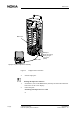
M aint enance M ainU nit L M P cabl e L M P port (frontconnect or) 9-w ay ' D 't y pe connect or (m al e) L apt op P .C (w it h S upervisorsoft w are) F igure 1. 4. L apt op t o M U connect ion Start the laptop PC. Starting the Supervisor software 1. In Windows, click on the Start button (normally located in the bottom left hand corner of the screen display. 2. Follow the path: Start\Programs\Supervisor Ver 1.0.
R epair Start\Programs\Supervisor Ver 1.0.1 When the software application starts, the main window appears normally (Figure ). F igure 2. InL it e S upervisorm ainw indow If the Supervisor software application is being invoked for the first time, however, the Com Port SetUp window will appear ( Figure ) instead of the main window.
M aint enance F igure 3. Com P ortS et up w indow N ot e The Nokia default setting is: 9600 Baud, 8NI (8 bit data, no parity bit, 1 stop bit). If this setting is to be changed, the Com port chosen should be a com port not used by other peripherals. If the com port chosen is already in use, an error message is issued telling the operator to choose another port. N ot e The Com Port setup window can also be accessed via the Configure button in the main window of the Supervisor software. 3.
R epair 3.1.2 Disconnecting the laptop PC Use this procedure to disconnect the laptop PC after all faults have been located, diagnosed, corrected and tested. To disconnect the laptop PC 3.2 1. Close the Supervisor software and shut down the laptop PC. 2. Disconnect the laptop PC and LMP cable from the MU. 3. Store the laptop in a secure location. 4.
M aint enance 3.3 MU 3.3.1 Locating a faulty unit To locate a faulty unit in the MU 3.3.2 1. Connect the laptop PC as described Section 3.1.1. 2. Start the Supervisor software application. 3. The LED icon of the faulty unit in the Supervisor software window will be coloured red. Replacing a faulty unit Relevant warnings and cautions are given in Nokia InLite: Warnings and Cautions. WARNING Advise all persons who perform operations on this equipment of the potential dangers.
R epair 8. Send the faulty unit to Nokia for repair, using the procedure advised by the local Nokia agent. The unit should be identified and accompanied by a fault statement. 3.4 Remote Unit 3.4.1 Localising an RU fault Normally, an RU fault is located with the use of the InLite Supervisor software application. However, an RU has two LEDs (green and red) that are visible externally. The LEDs are illuminated when the RU is in a fault state and not functioning.
M aint enance 16 (26) 3. Go to the Local Unit window of the ISMMan software. Use the ISMMan software to switch off the DL laser of the relevant LU. The colour of the LED icon will change to red. 4. Remove the four M3 x 20 fixing screws that secure the cable cover to the Remote Unit mounting rack. 5. Remove the cable cover. 6. Disconnect the power supply cable from the RU. 7. Disconnect the antenna cables from the RU. 8.
R epair 3.4.2.2 To replace a faulty RU IP53 WARNING Disconnect the power connector from the RU before performing this procedure. WARNING Shut down the laser in the LU connected to the RU that is to be replaced. Respect the laser radiation warnings. N ot e Refer to document Installation D N 00283717 Issue 2 D R A F T 1 -en 1. Connect the laptop PC to the MU as described in Figure . 2. Start the ISMMan software application. 3. Go to the Local Unit window of the ISMMan software.
M aint enance 3.4.2.3 16. Where applicable, set the RU power to ON at the mains switchboard or at the CPSU. 17. At the location of the replacement RU, verify that its power LED is lit (GREEN) and the red FAULT LED is unlit (dark) on the RU. 18. Use the ISMMan software to check that the alarm has disappeared. 19. Replace the cover by sliding it downwards from top of the backplate along the bars on both sides of it. 20. Secure the cover to the wall using one fixing screw. 21.
R epair 10. Very carefully draw the optic cables out of the enclosure through the hole they are fitted into the enclosure. 11. Remove the four M6 x 40 fixing screws which secure the enclosure to the wall. Caut ion RU IP64 weighs 11 kg so be very careful while removing the screws. 3.5 12. Lift the RU off the wall, then store in a safe place. 13. Obtain a known good RU and carefully place it on the wall. 14. Carefully support the RU and secure it to the wall using four fixing screws. 15.
M aint enance 20 (26) © N okia Corporat ion N okia P ropriet ary and Confident ial D N 00283717 Issue 2 D R A F T 1 -en
S y st em upgrades 4 System upgrades 4.1 Supervisor software To upgrade the Supervisor Software The procedure installs a new version of the Supervisor Software. 4.2 1. Check the version of the new CD-ROM 2. Insert the CD-ROM and run the “setup” file. System configuration An InLite system can comprise up to eight LUs and each LU can handle up to four RUs. The actual number of RUs installed can therefore vary between one and 32.
M aint enance 22 (26) © N okia Corporat ion N okia P ropriet ary and Confident ial D N 00283717 Issue 2 D R A F T 1 -en
F aul tfinding and cl earing 5 Fault finding and clearing 5.1 Fault finding Fault finding is arrange in two categories: 5.1.1 1. Coverage 2. Alarm indication. Loss of coverage The following table defines the extent of loss of coverage and the possible cause of this loss of coverage.
M aint enance Tabl e 1. 5.1.2 L oss of Coverage Alarms The following fault finding algorithm shows a procedure for interpreting alarms and methods for clearing them.
F aul tfinding and cl earing Al arm O N YE S L ocalU nit Al arm ? Is ita dow nl ink or upl ink al arm ? D L The L ocalU nit is faul t y YE S NO UL NO R em ot e U nit Al arm ? The l aseris faul t y orunderst ress Is t here an inputsignal ? YE S The faul tis int he fibre opt ic cabl e YE S A re t he opt ical connect ors cl ean? The fibre opt ic cabl e is eit herbroken ort he spl ices are notperfect . O TD R act ion is required F igure 4.
M aint enance 5.2 Cleaning optical connectors An optical connector is basically a lens, and its performance can be degraded by dust particles, finger grease and scratches. The surface of connector ferrule can be inspected by means of a microscope. To clean an optical connector 1. Open the connector. F igure 5. 2. S C /A P C m al e connect or Apply a drop of cleaning liquid (pure alcohol) to the edge of the ferrule, then clean and dry it carefully with a soft tissue, using a circular movement.