
User's Manual

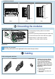

Connecting external power feed to system module
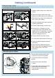
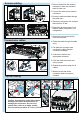
1. Install the cable clamp on the side of the
casing.
2. Remove the black rubber boots, nuts,
washers and cable lugs from the terminals.
3. Strip about 2 cm (.8 in) of insulation from
the (+) and (-) DC cables.
4. Insert the stripped end of each cable into
a cable lug and crimp.
5. Pull each cable through a rubber boot.
6a.Connect the (-) crimped wire to the
(-) connector pole, insert washer, and
tighten the nut. Connect the (+) crimped
wire to the (+) connector pole, insert
washer, and tighten the nut.
6b.Torque the M10 nuts (max 14 Nm).
7. Pull the black rubber boots over the lugs.
8. Route the cable through the external
cable entry.
9. Route the power cables through the
cable clamp, attach and tighten the cable
clamp screws with a T10 TORX
screwdriver.
Cabling (continued)
External power cables
1
2
cm
Cable
ends
Strip off about 2 cm
3
4
2
5
6a
7
8
9
6b
Internal power cables
1. Remove the connector seal on the
module to uncover the connector.
2. Connect the cable to the System
Module.
3. Push the connector seal firmly
in place.
4. Connect the other end of the internal
power cable to the RF Module.
Push the cable connector seal
firmly in place.