
User's Manual

6-73
For base station configuration, the serial interface connector lets you directly connect the
base station to a computer. The seven-pin connector is an RS-232 cable (10 ft.), physical
interface.
Serial interface connecting cable
Cable 597-6028-0010 has a female, circular connector on one end, and a DB-9 female
connector on the other end. Plug the DB-9 end of the cable into a computer. Plug the other
end of the cable into the serial interface connector.
Antenna connector
The antenna connector is a type N female connector. It has a built-in, internal 1/4 wave
lightning protector. Connect the base station to the antenna using a coaxial cable. Connect
the proper lightning ground wiring to the antenna lightning protector.
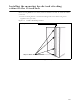
Connecting the antenna to the base station
This section provides tips you can use to connect the antenna to the base station for
installations where the antenna is not mechanically mounted to the Integrated Base Station
It also provides step-by-step instructions for connecting the components to each other.
Antenna connection tips
Use the following tips when connecting the base station to the antenna:
• You connect the antenna to the base station using a coaxial cable. The size of the cable
depends on the distance between the base station and the antenna.
• The greater the distance, the larger your coaxial cable needs to be, in order to maintain
low signal loss.
• It is recommended that you keep signal loss to a minimum. At a maximum, the signal
loss should be no more than 2 dB, including all coaxial cable and connectors.
• Use short coaxial jumpers from the base station to the main coaxial line, and from the
main coaxial line to the antenna. It is recommended you use 1/2 inch flexible line, of the
shortest length possible, while still allowing the flexibility to make a good connection.
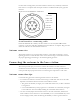
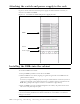
Figure 6.25 Serial interface connector
A Ground
B Not used
C Not used
D Not used
E Tx data
F Rx data
G Not used