
User's Manual

6-72 Configuring, Installing, and Using Carrier Infrastructure
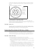
An RS-422 line also feeds 422Data+ and 422Data-, to allow data communication from the
GPS device to the base station. This is one-way communication, with the GPS device giving
the base station time information.
The 18V+ and ground pin supply power to the GPS device from the base station. The GPS
device uses 18 volts DC at 150 milliamperes.
Note: If you move the GPS receiver after supplying power to the GPS, you must reconfigure
the receiver using the Trimble synchronization kit.
GPS connecting cable/Inter-base station connecting
cables
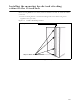
You need one GPS device per cell. You then directly connect one base station within that cell
to the GPS device. Next, the other base stations are connected to each other, using a daisy
chain wiring scheme, so that all base stations in the cell can receive a GPS signal.
You can choose the length of the cable that connects the base station to the GPS receiver.
You can also choose the length of the daisy-chain cable that connects one base station to
another base station.
• If you need to remove a base station for service, you can a longer cable to jumper the GPS
cables together, and continue cell operation.
The last base station in the daisy chain requires a load termination to be connected to the
GPS connection. This base terminator plug is 100 ohm (part number 515-6005-0001).
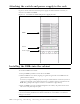
Serial interface connector
On the base station, the serial interface connector is green.
Table 6.4 GPS kits and cables
GPS kit part number Length of GPS cable
250-0150-0200 GPS system 200’
250-0150-0100 GPS system 100’
250-0150-0050 GPS system 50’
250-0150-0025 GPS system 25’
250-0150-0010 GPS system 10’
NOTE: The GPS kits listed in this table are for use with AMOD BTSs.
Table 6.5 Daisy chain cable choices
Part number Cable length
597-6026-0200 200 ft
597-6026-0100 100 ft
597-6026-0050 50 ft
597-6026-0025 25 ft
597-6026-0010 10 ft
597-6026-0004 4 ft
NOTE: The daisy chain cables listed in this table are for BTSs with the AMOD
feature.