
User's Manual

6-69
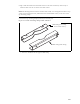
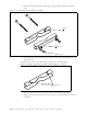
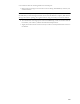
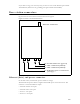
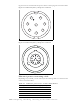
Table 6.2 describes the pins of the Ethernet/power cable that connects the base station to the
TVS device.
Table 6.3 describes the color and function of the wires in cable 597-6027-0xxx.
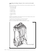
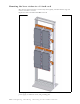
TVS module connectors
The TVS module has connectors on both its right and left sides.
597-6027-0050 50
597-6027-0100 100
597-6027-0200 200
597-6027-0300 300
Table 6.2 Ethernet/power cable pins
Pin TVS connection Base connection
1 Tx+ -48 VDC
2 Tx- -48 VDC
3 Rx+ +48 VDC
4 Rx- +48 VDC
5+48 VDC Rx-
6+48 VDC Rx+
7 -48 VDC not used
8 -48 VDC not used
9Tx-
10 Tx+
11 not used
12 not used
13 not used
Table 6.3 Function of wires in cable 597-6027-0xxx
Wire color Wire function
White/orange Tx+ Ethernet
Orange Tx- Ethernet
White/green Rx+ Ethernet
Green Rx- Ethernet
Red +48 VDC
Red/white +48 VDC
Black -48 VDC
Black/white -48 VDC
Table 6.1 Ethernet/power base station cable choices
Cable part number Length (feet)