
User's Manual

6-68 Configuring, Installing, and Using Carrier Infrastructure
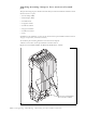
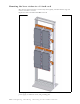
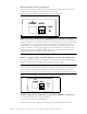
Figure 6.19 shows the Ethernet and power connector which plugs into the TVS module.
The connector to the base station has 13 pins.
Ethernet/power connecting cable
Depending on your needs, you can order any of the following cables to connect the base
station to the TVS module.
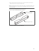
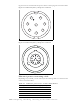
Figure 6.19 Ethernet (data) and power connector
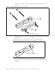
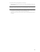
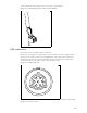
Figure 6.20 Ethernet (data) and power connector
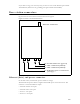
Table 6.1 Ethernet/power base station cable choices
Cable part number Length (feet)
597-6027-0002 2
597-6027-0004 4
597-6027-0006 6
597-6027-0010 10
597-6027-0025 25
8
1
2
3
4
5
6
7
1
2
3
4
5
6
7
8
9
10
11
12
13