
User's Manual

6-67
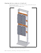
If you desire to stage your own relay rack, you must use two 19 inch brackets (part number
350-0100-0101) and at least one grounding plate (part number 30-0100-0020).
Base station connectors
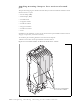
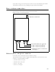
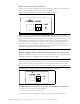
Figure 6.18 shows the connectors that the base station supports.
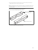
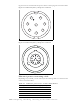
Ethernet (data) and power connector
On the base station, the Ethernet/power connector is orange.
The Ethernet and power connector supplies data and DC power to the base station. The
connector to the TVS module has 8 pins:
• Ethernet transmit uses 2 pins.
• Ethernet receive uses 2 pins.
• Power V- uses 2 pins.
• Power V+ uses 2 pins.
Figure 6.18 Base station connectors
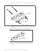
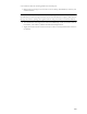
Antenna connector
J4—Serial connector (green)
J3—GPS connector (black)
J2—GPS connector (black)
J1—Ethernet/power connecto
r
(orange)