
User's Manual


6-50 Configuring, Installing, and Using Carrier Infrastructure
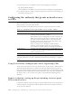
Cell wiring
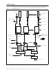
Figure 6.1 shows how a cell, base stations, and ancillary equipment are wired together.
Figure 6.1 Cell wiring diagram
1 2 6
Panel antenna
Coax jumper
Coax - main feed
Coax jumper
GPS unit
GPS Interface
cable
TVS
module
Backbone swtich Power supply
UPS
AC power cord
DC power cable
Base station
GPS inter-base
station cable
Ethernet/power
cable
Load
Termination
Optional serial
connection and
laptop computer
Backbone
connection cable
Ethernet
cable