
User's Manual


7-88 Configuring, Installing, and Using Carrier Infrastructure
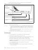
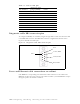
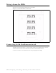
Diagnostic cable DB9 connector pins
To configure the RMBs, use a standard, straight-through cable. Connect one end of the cable
to the DB9 cable connector. The DB9 cable connector is supplied with the base station
Figure 7.8 describes the cable’s pins.
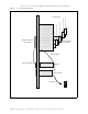
Fuses and Ethernet cable connections on cabinet
Each RMB has a corresponding fuse and Ethernet cable connection on the cabinet. The
RMB that occupies the lowest position in the cabinet is number 1, and the RMB that occupies
the highest point in the cabinet is number 8.
Pin 9 22 AWG White
Pin 10 22 AWG Green
Pin 11 18 AWG Red
Pin 12 18 AWG Red
Pin 13
Pin 14 18 AWG Red
Pin 15 18 AWG Red
Pin 16
Pin 17 18 AWG Red
Pin 18 18 AWG Red
Table 7.2 Power cable pins
Pin number
American wire
gauge (AWG) Color
Figure 7.8 Diagnostic cable: DB9 connector pins
Yellow/RXD
Green/TXD
Red/GND
Pin 1
Pin 6