
User's Manual


7-87
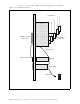
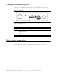
GPS connectors
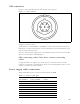
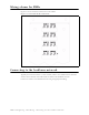
Figure 7.7 shows the GPS connectors that the base station supports.
An RS-422 line feeds 1PPS+ and 1PPS- with the time synchronization pulse from the GPS
equipment to the base station.
An RS-422 line also feeds 422Data+ and 422Data-, to allow data communication from the
GPS device to the base station. This is one-way communication, with the GPS device giving
the base station time information.
The 18V+ and ground pin supply power to the GPS device from the base station. The GPS
device uses 18 volts DC at 150 milliamperes.
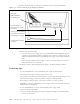
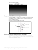
GPS connecting cable/Inter-base station connecting
cables
A single GPS device can support up to 8 base stations. You directly connect one GPS
connector on the cabinet to the GPS device. Then, on the remaining GPS connector on the
cabinet, you connect the load termination.
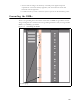
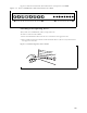
Power supply cable connections
Table 7.2 describes the pins of the power cable used with the RMB.
Figure 7.7 GPS connector
Table 7.2 Power cable pins
Pin number
American wire
gauge (AWG) Color
Pin 1 18 AWG Black
Pin 2 18 AWG Black
Pin 3
Pin 4 18 AWG Black
Pin 5 18 AWG Black
Pin 6
Pin 7 18 AWG Black
Pin 8 18 AWG Black