
User Manual

6-61
• The cable that comes standard in the base station site installation kit is 100 ft. (part number
597-6025-0100).
• If desired, you can use a shorter cable to connect the base station to the GPS receiver. This
alternate cable is 25 ft. (part number 597-6025-0025).
You can also choose the length of the daisy-chain cable that connects one base station to
another base station.
• The standard cable shipped in the base station installation kit is 3 ft. (part number 597-
6026-0003).
• If desired, you can use a longer cable to connect one base station to another. This cable is
10 ft. (part number 597-6026-0010)
• If you need to remove a base station for service, you can use the longer, 10 ft. cable to
jumper the GPS cables together, and continue cell operation.
The last base station in the daisy chain requires a load termination to be connected to the
GPS connection. This base terminator plug is 100 ohm (part number 515-6005-0001).
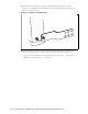
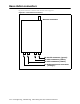
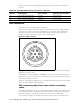
Serial interface connector
On the base station, the serial interface connector is green.
For base station configuration, the serial interface connector lets you directly connect the
base station to a computer. The seven-pin connector is an RS-232 cable (10 ft.), physical
interface.
Serial interface connecting cable
Cable 597-6028-0010 has a female, circular connector on one end, and a DB-9 female
connector on the other end. Plug the DB-9 end of the cable into a computer. Plug the other
end of the cable into the serial interface connector.
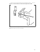
Antenna connector
The antenna connector is a type N female connector. It has a built-in, internal 1/4 wave stub
lightning protector. Connect the base station to the antenna using a coaxial cable. Connect
the proper lightning ground wiring to the antenna lightning protector.
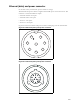
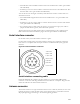
Figure 6.15 Serial interface connector
A Ground
B Not used
C Not used
D Not used
E Tx data
F Rx data
G Not used