
User Manual

6-60 Configuring, Installing, and Using Carrier Infrastructure
Table 6.4 describes the recommended mating connectors. The use of these connectors are
optional.
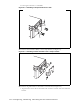
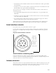
GPS connectors
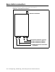
On the base station, the GPS connectors are black.
The base station supports two GPS connectors: one connector is used to supply the GPS
signal, either by a direct connection to the GPS device, or by a daisy chain connection to
another base station in the cell. The other GPS connector is used to make a daisy-chain
connection from the current base station to the next base station.
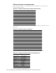
An RS-422 line feeds 1PPS+ and 1PPS- with the time synchronization pulse from the GPS
equipment to the base station.
An RS-422 line also feeds 422Data+ and 422Data-, to allow data communication from the
GPS device to the base station. This is one-way communication, with the GPS device giving
the base station time information.
The 18V+ and ground pin supply power to the GPS device from the base station. The GPS
device uses 18 volts DC at 150 milliamperes.
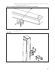
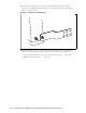
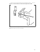
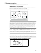
GPS connecting cable/Inter-base station connecting
cables
You need one GPS device per cell. You then directly connect one base station within that cell
to the GPS device. Next, the other base stations are connected to each other, using a daisy
chain wiring scheme, so that all base stations in the cell can receive a GPS signal.
You can choose the length of the cable that connects the base station to the GPS receiver.
Table 6.4 Recommended mating connectors (optional)
Ref des Description
Phoenix contact
part number Digi-key part number
J1 2pin, 5.08mm Terminal Plug 1757019 277-1011-ND
J3 4pin, 5.08mm Terminal Plug 1757035 277-1013-ND
J4 4pin, 3.81mm Terminal Plug 1803594 277-1163-ND
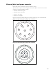
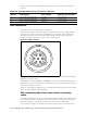
Figure 6.14 GPS connector
A
B
C
D
E
G
F