
User Manual

Index-94 Configuring, Installing, and Using Carrier Infrastructure
E
equipment
provided by service providers, 1-8
Ethernet
LED indicator, 7-77
Ethernet/power cable, 6-57
function of wires within, 6-57
splitting, 6-58
Expedience system
obtaining technical support for, preface-
xvii
F
fuses
replacing, 7-81
RMB, 7-80
G
GPS
components of, 6-63
connecting to base station, 6-64
connector, 6-59
daisy-chained base stations, 6-64, 7-78
determining validity of output, A-87
exposure requirements, 6-64
interface cable, 6-59, 7-78
mounting pole and socket, 6-64
powering, 6-64
status codes, A-87
TDD impact, 1-8
time pulse generated, 6-63
used to generate time signal, 5-46
GPS inter-base station cable, 6-59, 7-78
grounding
RMB, 7-76
H
Hyperterminal
using to configure base station, 5-32
I
indoor/outdoor base station
overview, 1-2
inter-base station cable, 6-59, 7-78
ISPs
defining names, 3-22
L
lightning protection, 1-9, 6-63
antenna, 6-60
supplied through TVS module, 6-58
links
selecting, 2-12
local authority
setting up, 5-46
LOS requirement elimination, 1-1
M
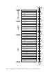
MMDS frequency range
channels, B-89
mounting
brackets, 6-61
template, 6-61
N
network access
setting up for CPEs, 5-44
NNOS web interface
setting base station configuration
parameters, 5-37
P
power supply
for RMB, 7-73
provisioning server
user interface
New User page, 3-20
R
rack
attaching switch and power supply, 7-70
remote authority
setting up, 5-45
RMB
cell wiring diagram, 7-72
diagnostic cable, 7-79
Ethernet cable connection, 7-80
fuses, 7-80
grounding, 7-76
installation overview, 1-5
installing in cabinet, 7-70
LED locations and meaning, 7-77
overview, 1-2
power cable connectors, 7-79
power connectors, 7-74
power supply requirements, 7-73
wiring to cell, 7-71
RS-232 cable, 5-32