
User's Manual


9
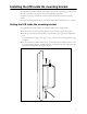
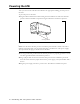
Connecting the GPS unit to the LPB and daisychaining other
LPBs in cell
One GPS unit can support numerous LPBs in the same cell.
1 When you connect the cable harness into the back of the LPB, the GPS unit is able to
receive its power from the base station. The GPS device uses 18 volts DC at 150
milliamperes.
2 So that the remaining LPBs in the cell can receive a GPS signal, connect an LPB adjacent
to the LPB you just connected to the GPS unit.
Continue to use the daisy chain wiring scheme to connect the remaining LPBs, until all of
the LPBs within the cell are connected to each other.
On the last LPB in the daisy chain, connect the load termination on the open GPS
connection.
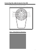
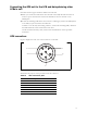
GPS connectors
Figure 5 displays the front view of the connectors on the GPS
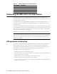
Table 2 lists the purpose of the pins that fit into the connector.
Figure 5 GPS connectors
Table 2 GPS connector pins
Pin number Purpose
1+1 PPS
2 -1 PPS
3 +422 data
4 -422 data
5GPS V+
6GND
1
4
5
3
6
2