
Datasheet


▲
Handling Instructions
▲
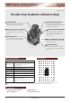
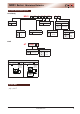
Typical Switch Dimensions
Areas marked indicate locations of the product’s metal parts (bracket). These should be taken into account when designing the circuit board pattern.
▼
Knobs are available separately.
▼
Terminal numbers are not marked on the switch body.
▼
Knobs are available separately.
▼
Terminal numbers are not marked on the switch body.
▼
Knobs are available separately.
▼
Terminal numbers are not marked on the switch body.
Areas marked indicate locations of the product’s metal parts (bracket). These should be taken into account when designing the circuit board pattern.
Areas marked indicate locations of the product’s metal parts (bracket). These should be taken into account when designing the circuit board pattern.
NR01103ANG13
Printed circuit board mounting-hole
dimension diagram
(Viewed from the switch-mounting side)
Model
Circuit & Position
Connected Position Number
Ⅰ Ⅱ Ⅲ
Ⅳ Ⅴ
NR01103ANG13 SP3T
C-2 C-3 C-4
ー ー
(1) and (5) are support terminals
NR01104ANG13 SP4T
C-2 C-3 C-4 C-5
ー
(1) is a support terminal
NR01105ANG13 SP5T
C-1 C-2 C-3 C-4 C-5
45° Indexing SP3T PC Bracket
NR01104ANG13
Printed circuit board mounting-hole
dimension diagram
(Viewed from the switch-mounting side)
45° Indexing SP4T PC Bracket
NR01105ANG13
Printed circuit board mounting-hole
dimension diagram
(Viewed from the switch-mounting side)
45° Indexing SP5T PC Bracket
2.542.54 5.08
10×1
3.53.5
1.5
4×2.54
2.542.54 5.08
10×1
3.53.5
1.5
4×2.54
2.542.54 5.08
10×1
3.53.5
1.5
4×2.54
(2)
(3)
(4)
(1)
(
C
)
(5)
45°
45°
10.7
10.7
Ⅰ
Ⅱ
Ⅲ
φ
9
φ
5.9
4x2.54
4.7
2
10.5
3.5
t 0.3
0.7
2.54
2.54
5.08
Product Code Marking Side
t 0.5
0.6
(1)
(
C
)
(5)
(2)
(3)
(4)
45°
45°
10.7
10.7
Ⅰ
Ⅱ
Ⅲ
45°
Ⅳ
φ
9
φ
5.9
4x2.54
4.7
2
10.5
3.5
t 0.3
0.7
2.54
2.54
5.08
Product Code Marking Side
t 0.5
0.6
(1)
(
C
)
(5)
(2)
(3)
(4)
φ
9
φ
5.9
4x2.54
4.7
2
10.5
3.5
t 0.3
0.7
2.54
2.54
5.08
Product Code Marking Side
t 0.5
0.6
45°
45°
10.7
10.7
Ⅰ
Ⅱ
Ⅲ
Ⅳ
Ⅴ
45°
45°
Knob Insertion
The knob is crimp-fitted onto the switch body and may become
detached if tampered with or pulled forcefully.
To prevent the knob from detaching, use AT3009A/C/H and
mount with the flange of the knob underneath the panel.
(See "Recommended panel mounting method.")
Recommended panel mounting method
Printed circuit board
Flange
Panel
NR01 Series
Miniature Rotaries
4
www.nkk.com