NX - rev A
i Table of Contents Page 1. Overview ........................................................................................................................................................................................... 1 2. Software Installation ........................................................................................................................................................................ 1 3. Software .......................................................................
1 1. Overview The BOOST REFERENCE PROGRESSIVE NITROUS CONTROLLER combines the functions of a throttle position switch, two RPM window switches, a MAP sensor and a 2 stage progressive driver all into a very compact module. It can progressively drive two channels, each with a 40 amp load capacity (continuous duty). The device also supports low-voltage OEM, V10 or 3 cylinder TACH signals without the need for additional adapters.
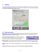
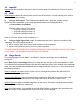
2 3. Software The following settings do not require that the controller be connected to the PC until you are ready to UPLOAD. All changes made to the set-up require that you UPLOAD to the controller before installing it in the vehicle. (See Upload/Download section). 3 .1 Entering User Data Drag & Slide – data fields that have this feature have a down arrow button to the right. Clicking and holding the button causes a slider bar to appear.
3 3 .2 Input #2 Input #2 tells the controller if this input is seen as active when it is connected to 12 volts or ground. 3 .3 RPM RPM Multiplier selects the correct pulse count for the RPM counter.
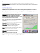
4 Solenoid Frequency is the rate at which the controller cycles the solenoids. This number is determined by the solenoid manufacturer. [14 will work with all solenoids but may not be the optimum frequency] 3.4.1 Time-Based Curve Present allows you to permanently turn off a stage. A check mark tells the controller to activate the stage as per the configuration. No check mark means this stage is always OFF.
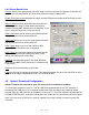
5 3.4.2 Boost-Based Curve Present allows you to permanently turn off a stage. A check mark tells the controller to activate the stage as per the configuration. No check mark means this stage is always OFF. Enable First-Gear Lockout disables the stage until the RPM has exceeded the RPM Cutoff at least once since it was armed. Input #2 will determines what effect this input will have on the applicable stage. Enable allows the stage to function normally while Disable turns the stage off.
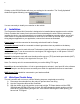
6 Clicking on the UPLOAD button will store your settings in the controller. The “Config Uploaded” window will appear following a successful upload. You are now ready to install your controller on the vehicle. 4. Installation The Progressive Nitrous Mini-Controller is designed to be installed almost anywhere on the vehicle. Select a location that is away from heat sources that can damage the wires.
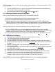
7 NOTE: The green LED on a new controller will flash when powered up. This indicates that the TPS is not programmed. 4) 5) Once the GREEN LED is out, open the throttle all the way by pressing the gas pedal to the floor and then release it. Repeat this step twice. Now verify that the GREEN LED goes off at IDLE and on at WOT. 4.1.
8 5. Software and Firmware Updates Free updates are available for the Progressive Nitrous Mini-Controller and related software at www.nitrousexpress.com 6. Disclaimer Nitrous Express, Inc shall not be held responsible for any damages, howsoever caused, to any persons or equipment during the installation or operation of its products. Nitrous Express products are meant for off-road use only, and make no claims as to the unit’s ability to meet local safety or emissions laws. 7.
Whi t e Whi t e-