
User guide


6
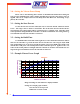
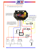
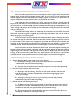
5.0—Single Nitrous-Fuel Solenoid Installation
5.1—Hold and Wait Style Progressive Timer
+
-
Battery
Chassis/Engine
Ground
Nitrous Arming
Switch
DPST
Fuse, 10 Amp
Fuse, 30 or
40 Amp
30
87
87A
85 86
+
-
Nitrous
Fuel Pump
Ground
16 GA Black
Safety
Solenoid
Nitrous
Solenoid
Fuel
Solenoid
To Nitrous BottleTo Engine
40 Amp Relay
Launch Switch
and/or
Line Lock
Throttle Switch
Ground
20 GA Black
Ground
16 GA Black
Solenoid +12V Supply, 14GA Red
Nitrous Feed Line
Nitrous Solenoid Ground, 14GA Blue
Fuel Solenoid Ground, 16GA Orange
C
NO
NC
IMPORTANT - The Nitrous and Fuel Solenoid
Grounds can be combined on either Output. This
will generally richen the mixture slightly due to the
Fuel Solenoid going to 100% sooner. This happens
because of the large EMF Voltage produced by the
higher amperage Nitrous Solenoid affecting the Fuel
Solenoid Operation.
Battery Ground, 14GA Black
Safety Relay Activation, 20GA Yellow
20 GA
Red
14 GA
Red
+12V Switched, 20 GA Red
20 GA Red
14 GA Red
14 GA Red
Activation +12V, 20GA Yellow
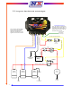
Note - The Red LED lamp should
be on steady with Arming Switch
ON and the Activation Signal OFF.
LED Lamp will blink when +12V is
applied to the Activation Terminal.
Note - The activation terminal has an
integrated resistor to Ground. This is to
insure that the Timing Retard Inputs of
popular Ignitions are OFF when the
Controller is NOT activated.
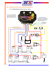
Timing Retard Activation
Connect to Timing
Retard Module
Activation Input