NX #15835 Installation & and User Guide 1
NX #15835 Table of Contents 1.0—Important Information 2.0—Controller Description, Basics of Operation 3.0—Setting the Nitrous Power Ramp 3.1—Setting the Start Percent 3.2—Setting the Build Time 3.3—Example Nitrous Power Graph 4.0—Installation Basics 5.0—Single Nitrous-Fuel Solenoid Installation 5.1—Hold and Wait Style Progressive Timer 5.2—Progressive Timer Reset with Activation Signal 6.0—Multiple Nitrous-Fuel Solenoid Installation 6.1—Hold and Wait Style Progressive Timer 6.
2.0—Controller Description and Basics of Operation The NX #15385, Nitrous Controller was designed to be a cost effective and accurate controller for the Application of Nitrous Power. By using the latest technology a .0000025 second resolution timer system is available for precise control of the solenoids. The programming switches are simple to use and provide binary coded information to the 32Mhz Microcontroller.
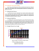
3.0—Setting the Nitrous Power Ramp Please refer to the following three sections for detailed information about Setting the Start percent and Build Time. These settings determine how aggressive the Nitrous Power is applied. There is an example Nitrous Power Ramp chart that shows how the Settings are applied by the controller. 3.1—Setting the Start Percent Use the Nitrous Start Percent switch (left one) to select the desired amount of Nitrous Power. The range is 20% to 50 in 2% increments.
4.0—Installation Basics Items Included with the NX #15835 Controller 1 - Wiring Harness 4 - Installation & User Manual Items needed that are NOT Supplied with Controller 1 - Nitrous Kit 2 - Safety Solenoid 3 - Activation Switches as needed, If not included with the nitrous kit. 4 - 40 Amp Relay, If not included with the nitrous kit.
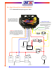
5.0—Single Nitrous-Fuel Solenoid Installation 5.1—Hold and Wait Style Progressive Timer Note - The Red LED lamp should be on steady with Arming Switch ON and the Activation Signal OFF. LED Lamp will blink when +12V is applied to the Activation Terminal. Timing Retard Activation Note - The activation terminal has an integrated resistor to Ground. This is to insure that the Timing Retard Inputs of popular Ignitions are OFF when the Controller is NOT activated.
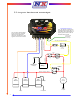
5.2—Progressive Timer Reset with Activation Signal Timing Retard Activation Note - The activation terminal has an integrated resistor to Ground. This is to insure that the Timing Retard Inputs of popular Ignitions are OFF when the Controller is NOT activated. Note - The Red LED lamp should be OFF with Arming Switch ON and the Activation Signal OFF. LED Lamp will blink when +12V is applied to the Activation Terminal.
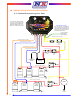
6.0—Multiple Nitrous-Fuel Solenoid Installation 6.1—Hold and Wait Style Progressive Timer Note - The Red LED lamp should be on steady with Arming Switch ON and the Activation Signal OFF. LED Lamp will blink when +12V is applied to the Activation Terminal. Timing Retard Activation Note - The activation terminal has an integrated resistor to Ground. This is to insure that the Timing Retard Inputs of popular Ignitions are OFF when the Controller is NOT activated.
6.2—Progressive Timer Reset with Activation Signal Note - The Red LED lamp should be OFF with Arming Switch ON and the Activation Signal OFF. LED Lamp will blink when +12V is applied to the Activation Terminal. Timing Retard Activation Note - The activation terminal has an integrated resistor to Ground. This is to insure that the Timing Retard Inputs of popular Ignitions are OFF when the Controller is NOT activated.
7.0—Testing Controller Operation and Trouble Shooting The controller operation can be tested with the vehicle engine OFF, Nitrous Fuel Supply OFF, and the Nitrous Supply (bottle) OFF. Never test the system with Fuel and Nitrous Supply ON, this will fill the non-running engine and can be very destructive to engine components and personnel when it is started the next time! After insuring that all supplies are OFF, turn On the Nitrous Arming Switch.
8.0—Specifications Normal Operating Voltage 10.0 to 18.0 Volts, Negative Ground Controller will Turn OFF at 6.2 Volts Solenoid Outputs 45 Amps Maximum each output Activation Input 125mA at 12.0 Volts Weight (approx) Overall Height Overall Width Overall Length .4 lb. 1.750 in. 3.125 in. 4.375 In. 9.0—Warranty Nitrous Express warrants to the original purchaser that the components shall be free from defects in parts and workmanship under normal use for 6 months from the date of purchase.