
Instruction Owner's manual


17
LVM-89W
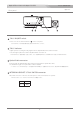
Input HD component signals. The input signals are displayed when the input select mode is set to the
COMP 1 mode.
HD/Y, HD/B-Y, HD/R-Y connectors (BNC)
CMP IN connector (BNC)
Input a composite video signal. The input signal is displayed when the input select mode is set to the
CVBS 1 mode.
CMP OUT connector (BNC)
Outputs the composite video signal. (Through output of the CMP IN input signal)
Input the tally signal( O∼2V=OFF, 2∼4V=GREEN, 4∼ V=RED ).
TALLY IN connector (BNC)
HD コンポーネント(HD/Y, HD/B-Y, HD/R-Y)信号を入力します。INPUT 切替ボタンをCOMP 1 に切り替えて表示します。
コンポジットビデオ信号を入力します。INPUT 切替ボタンをCVBS 1 に切り替えて表示します。
CMP IN コネクタに入力されたコンポジットビデオ信号をスルーで出力します。
タリー信号を入力します。タリー信号の電圧により、2∼4VのときGREEN, 4V以上のときREDが点灯します。
HDMI/HD Component Monitor LVM-89W/Universal Head
LVM-89W各部名称と働き
※カメラアダプターからのリターン信号(コンポジット)をモニターする場合は、リターン信号をこのコネクタに接続します。
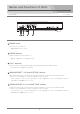
In order to monitor the return video signal(composite) from the camera adaptor, connect the signal
to this connector with BNC cable.
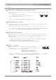
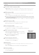
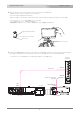
MONI IF connector (6-pin, female)
The DC 12V power and the tally signal are supplied from the Camera
Adaptor via the supplied 6-pin cable(VC-450).
1
2
3
4
6
GND
+12V IN
SG
NC
TALLY IN5
約650mA
0V=ON
※専用6ピンケーブルのみ使用可能です。
For the use of the supplied 6-pin cable only.
MONI IF connector
(6-pin, female)
Pin assignment
カメラアダプタから付属の6ピンケーブルを通して、12V電源、タリー信号が入力されます。
NC
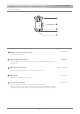
Connect an external DC 12V power. ( 10∼16V )
DC 12V IN connector (XLR 4-pin)
HDMI connector
Input a HDMI signal with HDMI cable. The input signal is displayed when the input select mode is set
to the HDMI mode.
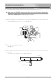
1/4 inch screw hole
Fix the supplied universal head.
DC 12V 電源( 10∼16V, AC アダプタ等)を接続します。
HDMI ケーブルでHDMI信号を入力します。これは、INPUTボタンで HDMI に切り替えて表示します。
ユニバーサルヘッドを取り付けます。