PS270/570 Operating Instructions Before operating the system, please read this manual thoroughly and retain it for future reference. Volume 1.5, 1st edition Ver. 3.
WARNING For the customers in the U.S.A. To reduce the risk of fire or electric shock,do not expose this apparatus to rain or moisture. This equipment has been tested and found to comply with the limits for a Class A digital device, pursuant to Part 15 of the FCC Rules. These limits are designed to provide reasonable protection against harmful interference when the equipment is operatedin a commercial environment.
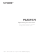
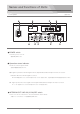
Optical Fiber Camera Adapter PS-270 PS-270 各部名称と働き Connector panel コネクタパネル GENLOCK output connector Output the Genlock reference signal to the camcorder. GENLOCK信号を出力するコネクタです。 REMOTE connector Connect with the remote control unit, SONY RM-B150,B750, and connect to the camcorder by the supplied 8-pin remote cable. ソニー社製RM-B150,750に適合するコネクタです。RCC-450(付属)を使ってカメラと接続します。 LANC connector Output the remote control signal to a SONY camcorder equipped with the LANC terminal (φ2.5 mini-jack).
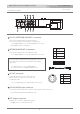
Names and Functions of Parts Optical Fiber Base Station PS-570 PS-570 各部名称と働き Front panel 前面パネル EXT LINE (4W I/O) INTERCOM HEADSET 4W I/O POWER switch Turns the power on or off. 電源をON/OFFします。 Operation status indicator Shows the current system status. 光信号の通信状況を表示します。 HD : Lights up when the HD-SDI signal from the Optical Fiber Camera Adaptor PS-270 is received. LED OFF : When the SD-SDI signal is received.
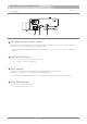
Optical Fiber Camera Adapter PS-270 Front panel 前面パネル DC12 VOUT connector (XLR-4, female) Outputs DC12V power supplied from the Optical Fiber Base Station PS-570 for a camera light, a monitor, a prompter, and etc.(the maximum electric power is 30W) PS-570から供給される12V系電源を出力するキャノン4Pメス出力です。カメラ、カムライト、LCDモニター等の電源に 使用します。 MONITOR OUT connector Connect to the monitor by the supplied 6-pin cable.
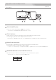
Optical Fiber Camera Adapter PS-270 Rear panel 背面パネル TALLY ON/OFF switch Turns on or off the TALLY indicator on the rear panel. リアパネルのタリー表示を任意に点灯/消灯するためのスイッチです。 TALLY indicator Lights up when receiving the tally signal from the Optical Fiber Base Station PS-570. It doesn t light up when the TALLY ON /OFF switch is turned off. PS-570からタリー信号を受けて点灯します。タリー表示ON/OFFスイッチをOFFにすると消灯したままになります。 Optical Cable connector Connects with the Optical Fiber Base Station PS-570 with an optical fiber cable.
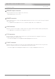
Optical Fiber Camera Adapter PS-270 Connector panel コネクタパネル DC12V /INTERCOM HEADSET 1 connector Connect the supplied Intercom headset DL-400. Or connect the DC12V power supply for DC operation. インカムを使用する場合にヘッドセット (DL-400)を挿入するコネクタです。 DC12V電源を入力することが可能です。 INTERCOM HEADSET 2 connector Connects the supplied Intercom headset DL-400. インカムを使用する場合にヘッドセット (DL-400)を挿入するコネクタです。 In case using the headset with the XLR-4P Male connector, make and use the cable with the XLR-4P Female-Female connectors.
Optical Fiber Camera Adapter PS-270 Connector panel コネクタパネル GENLOCK output connector Output the Genlock reference signal to the camcorder. GENLOCK信号を出力するコネクタです。 REMOTE connector Connect with the remote control unit, SONY RM-B150,B750, and connect to the camcorder by the supplied 8-pin remote cable. ソニー社製RM-B150,750に適合するコネクタです。RCC-450(付属)を使ってカメラと接続します。 LANC connector Output the remote control signal to a SONY camcorder equipped with the LANC terminal (φ2.5 mini-jack). ソニー社製LANCリモコンに対応するリモコン用φ2.
Names and Functions of Parts Optical Fiber Base Station PS-570 Front panel 前面パネル EXT LINE (4W I/O) INTERCOM HEADSET 4W I/O POWER switch Turns the power on or off. 電源をON/OFFします。 Operation status indicator Shows the current system status. 光信号の通信状況を表示します。 HD : Lights up when the HD-SDI signal from the Optical Fiber Camera Adaptor PS-270 is received. LED OFF : When the SD-SDI signal is received.
Optical Fiber Camera Adapter PS-270 PS-270 各部名称と働き Connector panel コネクタパネル DC12V /INTERCOM HEADSET 1 connector Connect the supplied Intercom headset DL-400. Or connect the DC12V power supply for DC operation. インカムを使用する場合にヘッドセット (DL-400)を挿入するコネクタです。 DC12V電源を入力することが可能です。 INTERCOM HEADSET 2 connector Connects the supplied Intercom headset DL-400.
Optical Fiber Camera Adapter PS-270 PS-270 各部名称と働き Rear panel 背面パネル TALLY ON/OFF switch Turns on or off the TALLY indicator on the rear panel. リアパネルのタリー表示を任意に点灯/消灯するためのスイッチです。 TALLY indicator Lights up when receiving the tally signal from the Optical Fiber Base Station PS-570. It doesn t light up when the TALLY ON /OFF switch is turned off. PS-570からタリー信号を受けて点灯します。タリー表示ON/OFFスイッチをOFFにすると消灯したままになります。 Optical Cable connector Connects with the Optical Fiber Base Station PS-570 with an optical fiber cable.
Optical Fiber Camera Adapter PS-270 PS-270 各部名称と働き Front panel 前面パネル DC12 VOUT connector (XLR-4, female) Outputs DC12V power supplied from the Optical Fiber Base Station PS-570 for a camera light, a monitor, a prompter, and etc.(the maximum electric power is 30W) PS-570から供給される12V系電源を出力するキャノン4Pメス出力です。カメラ、カムライト、LCDモニター等の電源に 使用します。 MONITOR OUT connector Connect to the monitor by the supplied 6-pin cable.
Names and Functions of Parts Optical Fiber Camera Adapter PS-270 PS-270 各部名称と働き Main panel メインパネル POWER switch Turns the power on and off. 電源をON/OFFするスイッチです。 POWER indicator Lights up when the power switch is on. 電源スイッチがONになっている時に点灯します。 TALLY indicator Lights up when receiving the tally signal from the Optical Fiber Base Station PS-570. PS-570からのタリー信号を受けて点灯します。 INCOM HEADSET 1 H.
Table of contents Optical Fiber Studio System NIPROS LS−270 & LS−570 Names and Functions of Parts PS-270 PS-570 4 Main panel 4 Front panel 5 Rear panel 6 Connector panel 7 Front panel 9 Rear panel 11 LVM-89W/Universul Head 14 System Connection 19 Pre-adjustment and Setting 28 System Connection Guide 31 Multi-Camera System Connection Guide 32 Outside View and Dimensions PS-270 33 PS-570 34 LVM-89W 35 Specifications 仕様 PS-270 36 PS-570 37 LVM-89W 38 03
HDMI/HD Component Monitor LVM-89W/Universal Head LVM-89W 各部名称と働き LVM-89W FRONT TALLY and REAR TALLY display select switch The brightness of the TALLY indicators on the front and rear panels can be selected by the select switches as follows. H : The tally indicator lights up brightly. L : The tally indicator is dimmed to the lower brightness. OFF : The tally indicator is turned off.
HDMI/HD Component Monitor LVM-89W/Universal Head LVM-89W各部名称と働き LVM-89W Function buttons PEAKING 16:9 MARKER RGB 4:3 COLOR INPUT MONO INPUT select button : Select the input signal connected to the HD (Y/B-Y/R-Y) component, CMP IN (composite signal input), and HDMI connector. By pressing INPUT button, select the input mode in sequence. The selected mode is displayed on the screen.
HDMI/HD Component Monitor LVM-89W/Universal Head LVM-89W各部名称と働き LVM-89W HD/Y, HD/B-Y, HD/R-Y connectors (BNC) Input HD component signals. The input signals are displayed when the input select mode is set to the COMP 1 mode. HD コンポーネント(HD/Y, HD/B-Y, HD/R-Y)信号を入力します。INPUT 切替ボタンをCOMP 1 に切り替えて表示します。 CMP IN connector (BNC) Input a composite video signal. The input signal is displayed when the input select mode is set to the CVBS 1 mode.
HDMI/HD Component Monitor LVM-89W/Universal Head LVM-89W 各部名称と働き Universal Head Monitor Lock Screw(1/4 inch) モニター固定ネジ Used to fix the monitor. Angle Adjustment Knob 角度調節ノブ Used to adjust the monitor position to any angle so that the display can be watch well. Slide-Shoe Lock Knob スライドシュー固定ノブ Used to fix the Slide Shoe to a camera accessory shoe. Slide-Shoe スライドシュー Slide into a camera accessory shoe. 1/4 inch Screw Hole 1/4インチネジ穴 Used to be fitted up with a 1/4 inch camera screw (male).
System Connection Optical Fiber Studio System NIPROS PS−270 & PS−570 Make sure the POWER switches of each unit are off before connection 接続する前に、各機器の電源スイッチは必ず OFF にしてください。 1 Fix the PS-270 tightly to the bottom surface of the camcorder PMW-EX3 with the camera screw (w1/4). PMW-EX3の底面にPS-270 をカメラネジでしっかり締めて固定します。 PMW-EX3 PS-270 2 Fix the camcorder PMW-EX3 to a tripod. 三脚に装着します。 3 Fix the supplied universal head to the screw hole on the bottom surface of the monitor with the Monitor Lock Screw.
System Connection 4 NIPROS PS−570 Slide the monitor to the stop position of the accessory shoe of PMW-EX3. Tighten the Slide-Shoe Lock Knob to fix the monitor. Loosen the Angle Adjustment Knob and adjust the angle of the monitor so that the monitor can be watched easily, then tighten the knob again.
System Connection 6 NIPROS PLS−570 Connect the HD-SDI/ SD-SDI input connector with the HD-SDI output connector of the camcorder by a BNC cable PS-270のHD-SDI/SD-SDIコネクタへカメラのHD-SDI/SD-SDI出力からBNCケーブルで接続します。 PS-270 HD-SDI/SD-SDI input connector 7 HD-SDI/SD-SDI output connector In case of using Genlock reference signal, connect the GENLOCK output connector to the input connector of the camcorder by a BNC cable.
System Connection 9 NIPROS PS−570 Connect the REMOTE connector to the camcorder by the supplied 8-pin remote cable. PS-270のREMOTEコネクタからカメラのREMOTE端子へ専用8Pケーブル(RCC-450)で接続します。 REMOTE connector PS-270 10 8Pケーブル(RCC-450) Connect the DC OUT connector to the DC IN connector of the camcorder by the supplied DC cable. PS-270のDC OUTコネクタからカメラのDC INコネクタへDCケーブル(DC-EX3)で接続します。 DC OUT connector PS-270 DCケーブル(DC-EX3) DC input connector 11 Connect the supplied Intercom headset DL-400 to the HEADSET connector.
System Connection 12 NIPROS PS−570 Connect the HD-SDI/SD-SDI OUT connector to a switcher, a monitor or a video recording equipment by a BNC cable. PS-570のHD-SDI/SDI OUTコネクタからスイッチャー、レコーダーもしくはモニターへBNCケーブルで接続します。 PS-570 to switcher, monitor, VTR, etc. 13 HD-SDI/SDI OUT connector Connect the RET IN connector with a switcher to input the return video signal(composite) by a BNC cable. RET INコネクタにRET信号(コンポジット信号)をBNCケーブルで接続します。 PS-57 RET IN connector from switcher, etc.
System Connection 15 NIPROS PS−570 Connect the the SONY remote controller to the REMOTE connector by the supplied 8-pin remote cable. リモコンを使用するときはREMOTEコネクタへソニー社製のリモコンをリモコンに付属しているケーブルにて接続します。 PS-570 REMOTE connector 16 In case of the multi-camera operation, connect the INCOM connector with the INCOM connector of other PS-570 by a BNC cable.
System Connection 18 NIPROS PS−570 In case of using Time Code, connect the TC IN/OUT connector to the time code out/in of an external recording equipment. TC INにVTR等のTC OUT信号を、TC OUTにVTR等のTC IN信号を接続します。 PS-570 TC IN/OUT connector 19 Connect an external 2 wire intercom line to the INCOM 2W connector. Connect an external 4 wire intercom line to the AUX/INCOM 4W connector.
System Connection 21 NIPROS PS−570 Connect the Intercom headset DL-400 to the INCOM (Intercom headset) connector インカムコネクタにヘッドセット(DL-400)を接続します。 EXT LINE (4W I/O) INTERCOM HEADSET 4W I/O INCOM connector DL-400 26
System Connection 22 NIPROS PS−570 Connect an optional Optical fiber cable to the OPT CABLE connector of PS-270. PS-270コネクタパネルの光ケーブルコネクタからPS-570へ光ケーブル(別売AC-100M)を接続します。 PS-270 OPT Cable connector Connect the OPT CABLE connector of PS-570 with an optional Optical fiber cable from PS-270.
Pre-Adjustment and setting Optical Fiber Studio System NIPROS PS−270 & PS−570 Turn on the power switches of PS-270,PS-570 and PMW-EX3 Make sure the volume of each unit is set to the minimum position before starting adjustment. Never turn up the volumes suddenly to prevent hearing impairment.
Pre-Adjustment and Setting NIPROS PS−570 PS-570 EXT LINE (4W I/O) HEADSET INTERCOM 4W I/O DL-400 Volume 1 Volume Put on the Intercom headset DL-400 インカムヘッドセットDL-400を装着します。 2 While listening your voice and the cameraman s, turn up the MIC volume and H.P volume gradually so that you can hear both voices clearly. Turn down the SIDE TONE volume slightly. H.P.
Pre-Adjustment and Setting NIPROS PS−570 Setting 1 Select Tally indication channels of PS-570 with TALLY SELECT switches. Make sure the TALLY indicator lights up correctly when the corresponding tally channels of a switcher are selected. PS-570の前面パネルにあるスイッチをタリー選択時に点灯するように設定したいチャンネルのみONにします。 Set the switch(s) to ON to light up the TALLY indicator(s) of selected channel(s).
System Connection Guide Optical Fiber Studio System NIPROS PS−270 & PS−570 N I P R O S PS−270/570 O P TI C A L FIBER STUDIO SYSTEM CLASS 1 LASER PRODUCT System Connection Guide HEAD SET DL-400 2 VF6PIN CABLE VC-450 1 ~~~ /~j~~ ACj~ ~ .I REMOTE CABLE RCC-450 1 BNC CABLE 38cm 3 BNC CABLE 1m 1 DC CABLE DC-EX3 1 D-SUB15PIN-D-SUB 15PIN 1 D-SUB15PIN-CUT 1 \~ LANC CONTROL CABLE 1 付属品 I Option DC CABLE g " ~ ~ /" . DCケーブル . ~ RCC-450 DL-400 -,.:::~ ....' .. ::.
Multi-Camera System Connection Guide Optical Fiber Studio System NIPROS PS−270 & PS−570 ●Camera 1 ●Monitor ●BNC cable ●Headset DL-400 ●6-Pin cable VC-450 PEAKING 16:9 MARKER RGB 4:3 Tally/Return/Genlock Switcher COLOR INPUT MONO ●PMW-EX3 HD-SDI 2/SD-SDI ●Rack Mount kit HS-RA90 Tally/Return ●HD-SDI cable (BNC) ●Gen Lock cable (BNC) Incom Connector Tally/Return/Power/Incom/Genlock/Remocon EXT LINE (4W I/O) INTERCOM HEADSET 4W I/O Blank panel HD-SDI/SD-SDI/Incom ●PS-270 Dedicated cable (Supp
Outside View and Dimensions 179 Optical Fiber Camera Adapter PS-270 (front) (rear) 59 266 (connector panel) Outside dimension (unit: mm) 外形寸法図(単位:ミリ) 33
Outside View and Dimensions 320 Optical Fiber Base Station PS-570 EXT LINE (4W I/O) INTERCOM HEADSET 71 215 4W I/O (rear) Outside dimension (unit: mm) 外形寸法図(単位:ミリ) 34
Outside View and Dimensions HDMI/HD Component Monitor LVM-89W/Universal Head 35mm 217mm HD/Y HD/B-Y 149mm HD/R-Y CMP IN CMP OUT TALLY IN MONI IF PEAKING 16:9 MARKER RGB COLOR INPUT DC 12V IN MONO 52mm 4:3 Outside dimension (unit: mm) 外形寸法図(単位:ミリ) 35
Specifications Optical Fiber Camera Adapter PS-270 Output Time Code BNC x1 Return BNC x1: 1Vp-p, 75Ω, Anaglog composite or HD-Y ※1 Genlock (Prompter) BNC x1: 1Vp-p, 75Ω, self-detecting, dual purpose Genlock/Teleprompter output, composite or HD-Y (down grade compared to standard HD signal) DC out Total 50W ※2 XLR 4pin(female) x1: 13.5V 3.5A (Maximum 13.7V, 3.5A) Mini 4pin(female) x1: DC 8.4V (Maximum 8.7V)or DC12V(Maximum 13.7V) Monitor Mini 6pin(female) x1: 13.5V 150mA (Maximum 13.
Specifications Optical Fiber Base Station PS-570 Output HD/SD-SDI BNCx2: Audio,T/C embedded Tally D-sub 15pin x1 Time Code OUT BNC x1 Headset XLR 4 pin x1 Input Return signal BNCx1: Composite or HD-Y Time Code IN BNC x1: Genlock ※1 BNCx1: Composite or HD-Y Tally D-sub 15pin x1 DC XLR 4pin(male)x1: DC 12V Incom Incom XLR 3pin x1: 2W for Clearcom XLR 5pin x1: 4W Incom, IN:-10db to +4dB,OUT:-10dB BNC x1 Remote Remote 8pin ※2 LANC Stereo mini-jack Φ2.
Specifications HDMI/HD Component Monitor LVM-89W/Universal Head LVM-89W Size 画面サイズ 8.9 inch-type 8.
PS-270 / PS-570 Operating Instructions