Optical Fiber Studio System 光コンバージョンシステム Optical Fiber Camera Adaptor カメラアダプター Optical Fiber Base Station ベースステーション PS-470/1 PS-570/1 Operating Instructions Before operating the system, please read this manual thoroughly and remain it for future reference. 取扱説明書 ご使用の前に、この取扱説明書をよくお読みください。 また、お読みになった後は、大切に保管してください。 Volume1, 1st edition Ver. 1.
For the customers in the U.S.A. WARNING This equipment has been tested and found to comply with the limits for a Class A digital device, pursuant to Part 15 of the FCC Rules. These limits are designed to provide reasonable protection against harmful interference when the equipment is operatedin a commercial environment.
Contents Optical Fiber Studio System PS-470/1 PS-570/1 Names and Functions of Parts PS-470/1 PS-570/1 目次 4 各部名称と働き PS-470/1 Main panel 4 Connector panel 6 メインパネル コネクタパネル PS-570/1 Front panel 9 Rear panel 11 Connection 14 Adjustments and Settings 28 System Connection Guide 30 Multi-Camera System Connection Guide 31 フロントパネル リアパネル 接続方法 調整及びセッティング システム接続ガイド マルチカメラシステム接続ガイド Outside View and Dimensions / Specifications 外形寸法図・仕様 PS-470/1 32 PS-570/1 34 03
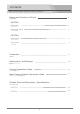
Names and Functions of Parts PS-470/1 各部名称と働き Optical Fiber Camera Adaptor PS-470/1 Main panel メインパネル INCOM MIC MINI MAX MINI MAX H.
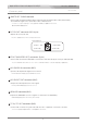
Optical Fiber Camera Adaptor PS-470/1 PS-470/1 各部名称と働き Main panel メインパネル POWER Switch Turn the power on and off the power supplied from the Optical Cable, Litium Battery Pack, or the DC 12V IN connector. OPTケーブル, リチウムイオンバッテリーパック, またはDC 12V IN コネクタから供給された電源をON/OFF します。 INCOM Volume Adjust the MIC level and the HEADPHONE level of the HEADSET( DL-400 ) connected to the INCOM HEADSET connector( ).
Optical Fiber Camera Adaptor PS-470/1 PS-470/1 各部名称と働き Connector panel コネクタパネル TALLY DC OUT IF OUT REMOTE L GEN LOCK HD-SDI RET OUT HD-SDI/ SDI IN TC IN TC OUT MADE IN JAPAN 06
Optical Fiber Camera Adaptor PS-470/1 PS-470/1 各部名称と働き Connector panel コネクタパネル SMPTE OPT CABLE connector Connect with the Optical Adapter Base Unit PS-570 by the Optical fiber cable( ALC-100M, ). The maximum length of the optical fiber cable is 2000 meters. ベースステーション(PS-570)と光ケーブル (別売ALC-100M等) にて接続するコネクタです。 最大2000Mまで使用可能です。 DC12V OUT connector (XLR 4-pin) Outputs the power, DC 12V.
Optical Fiber Camera Adaptor PS-470/1 PS-470/1 各部名称と働き Connector panel コネクタパネル REMOTE L ( LANC ) connector (φ2.5 mini jack) Connect with the camera equipped with the LANC terminal(φ 2.5). LANC リモコンを使用する場合にミニプラグケーブルを接続するコネクタです。 REMOTE connector Connect to a camera by the supplied remote cable RCC-450 i/P/S when using the camera remote controller made by the camera manufacturer.
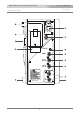
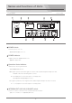
Names and Functions of Parts Optical Fiber Base Station PS-570/1 PS-570/1 各部名称と働き Front panel フロントパネル EXT LINE (4W I/O) INTERCOM HEADSET 4W I/O POWER Switch Turns the power on or off. 電源のON,OFFを切換えるスイッチ。 POWER Indicator Lights up when the POWER switch is on. 電源ONのとき点灯します。 Operation Status Indicator Indicates the current system status. 光信号の通信状況を表示します。 HD : Lights up when the HD-SDI signal is received from the Camera Optical Adaptor PS-470. LED OFF : When the SD-SDI signal is received.
Optical Fiber Base Station PS-570/1 PS-570/1 各部名称と働き Front panel フロントパネル TALLY SELECT Switch Selects the tally channel and the TALLY SELECT switch to the ON position to light up the TALLY indicator. タリーを点灯させるチャンネル1∼5CHのスイッチを選択してONします。 TALLY Indicator Lights up according to the setting of the TALLY SELECT switch when tally signal is input to the TALLY IN connector on the rear panel.
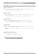
Optical Fiber Base Station PS-570/1 PS-570/1 各部名称と働き Rear panel リアパネル HD-SDI RET IN TALLY IN connector (HD D-sub 15-pin, female) Input the tally signal from a switcher.
Optical Fiber Base Station PS-570/1 PS-570/1 各部名称と働き Rear panel リアパネル RET IN connector (BNC) Input the RET signal (composite or HD-Y) from a switcher. Input the appropriate signal according to the VF of the camera connected to the CA. The input signal is output from the IF OUT connector of PS-470. RET映像(コンポジットまたはHD-Y 信号)を入力します。カメラのVFの入力に合わせて入力します。 この信号はPS-470の IF OUTコネクタ(6-pin)から出力されます。 GENLOCK connector (BNC) Input the Genlock reference signal from an external signal generator.
Optical Fiber Base Station PS-570/1 PS-570/1 各部名称と働き Rear panel リアパネル HD-SDI/SDI OUT connector (BNC) Outputs the HD-SDI or SD-SDI signal from the Optical Fiber Camera Adaptor PS-470. Signal format, HD or SD is indicated at the Operation status indicator ( ). 光カメラアダプタ(PS-470)に入力されたHD-SDIまたはSD-SDIの信号が出力されます。 HDかSDかがOperaton status indicator に表示されます。 HD-SDI/SDI RET IN connector (BNC) Inputs the HD-SDI or SD-SDI signal from a switcher, etc.
Connection Optical Fiber Studio System PS-470/1 PS-570/1 PS-470/1 PS-570/1 接続方法 Make sure to turn off the POWER switch of each unit before connecting. 接続する前に必ず各機器の電源スイッチを OFFにしてください。 Mount on the tripod 1 三脚への取り付け Fix the Camera Adaptor PS-470 to the V-shoe mount of the camera. カメラのVシューマウントにPS-470を固定します。 2 Mount the camcorder on a tripod.
Connection PS-470/1 PS-570/1 接続方法 HD-SDI video signal connection 1 HD-SDI ビデオ信号の接続 Connect the HD-SDI/ SD-SDI IN connector and the HD-SDI output connector of the camera with a BNC cable PS-470のHD-SDI/SD-SDIコネクタへカメラのHD-SDI/SD-SDI出力からBNCケーブルで接続します。 TALLY DC OUT IF OUT REMOTE L GEN LOCK HD-SDI/ SD-SDI IN HD-SDI RET OUT HD-SDI/ SDI IN from camera HD-SDI/SD-SDI OUT TC IN MADE IN JAPAN TC OUT HD-SDI RET IN HD-SDI/SDI OUT connector to monitor (HDF-700, etc.) switcher, etc.
Connection PS-470/1 PS-570/1 接続方法 RETURN HD-SDI video signal connection 1 リターンHD-SDIビデオ信号の接続 Connect the HD-SDI RET OUT connector to a monitor, etc. with a BNC cable. HD-SDI リターンビデオ信号の出力は、HD-SDI RET OUT コネクタからモニター等へ BNC ケーブルで接続します。 TALLY DC OUT IF OUT REMOTE L GEN LOCK HD-SDI RET OUT HD-SDI RET OUT (BNC) HD-SDI return video signal HD-SDI/ SDI IN to monitor HDF-700 etc. TC IN MADE IN JAPAN TC OUT HD-SDI RET IN HD-SDI RET IN connector return HD-SDI video signal 2 from switcher, etc.
Connection PS-470/1 PS-570/1 接続方法 RETURN composite video signal connection 1 リターンコンポジットビデオ信号の接続 When using the monitor LVM-89W, connect the IF OUT(monitor interface) connector of PS-470 to the MONI IF connector of LVM-89W with the 6-pin cable(VC-450).
Connection PS-470/1 PS-570/1 接続方法 RETURN composite video signal connection リターンコンポジットビデオ信号の接続 In case of using the viewfinder to display the return signal 3 Fit up the viewfinder interface unit(VIF-100,optional) to the camcorder and connect the viewfinder, the viewfinder interface unit, PS-470 and the camcorder.
Connection PS-470/1 PS-570/1 接続方法 GENLOCK signal connection 1 GENLOCK信号の接続 Connect the GENLOCK connector to the GENLOCK input connector of the camera with a BNC cable. PS-470のGENLOCKコネクタからカメラのGENLOCK INコネクタへBNCケーブルで接続します。 2 Connect the GENLOCK connector to a Genlock reference signal generator with a BNC cable.
Connection PS-470/1 PS-570/1 Time Code signal connection 1 TC信号の接続 Connect the TC IN/OUT to the time code in/out connector of the external recording equipment. TC INにVTR等のTC OUT信号を、TC OUTにVTR等のTC IN信号を接続します。 TC IN/OUT connector from VTR, etc. 接続方法 TC signal to VTR, etc.
System Connection PS-470/1 PS-570/1 接続方法 REMOTE control connection 1 リモコンの接続 Connect the REMOTE connector of PS-470 to the REMOTE connector of the camcorder with the camera remote cable(RCC-450S/P). PS-470のREMOTEコネクタからカメラのREMOTE端子へ専用カメラリモートケーブル(RCC-450S/P)で接続します。 2 Connect the REMOTE connector of PS-570 to a camera remote controller by the camera remote cable supplied with the remote controller..
System Connection PS-470/1 PS-570/1 接続方法 LANC control connection 1 LANCリモコンの接続 Connect the REMOTE L connector of PS-470 to the LANC remote connector of the camera with the LANC control cable. PS-470のREMOTE LコネクタからカメラのLANC端子へLANCリモートケーブルで接続します。 2 Connect the REMOTE L connector of PS-570 to a LANC remote controller by the LANC remote cable supplied with the remote controller..
Connection PS-470/1 PS-570/1 接続方法 TALLY signal connection 1 タリー信号の接続 Input the tally signals to the TALLY IN connector connecting to a switcher by the HD D-sub 15-pin cable. In case of multi-camera operation, connect the TALLY OUT connector to other PS-570 by the HD D-sub 15-pin multi cable. タリー表示を行う場合はTALLY INにスイッチャー等からの信号をHD D-sub15P-15Pケーブルで接続します。 複数台のPS-570を接続する場合はTALLY OUT を他のPS-570へHD D-sub15P-15Pケーブルで接続します。 TALLY TALLY OUT DC OUT INCOM to HDF-700 MIC MINI MAX MINI MAX MINI MAX H.
Connection PS-470/1 PS-570/1 接続方法 INTERCOM line connection 1 インターカムの接続 In case of the multi-camera operation, connect the INCOM connector to the INCOM connector of other PS-570 with a BNC cable. INCOMを他のPS-570と接続する場合はINCOMコネクタにBNCケーブルで接続します。 INCOM connector PS-570/1 BNC cable PS-570/1 2 Connect an external 2 wire intercom line to the INCOM 2W connector(XLR 3-pin). Connect an external 4 wire intercom line to the AUX/INCOM 4W connector(XLR 5-pin).
Connection PS-470/1 PS-570/1 接続方法 Power Supply connection 1 電源の接続 Connect the supplied AC power cable to the AC in connector of PS-570. And connect an optical fiber cable to both the OPT connectors of PS-470 and PS-570. 電源ケーブルをPS-570のACコネクタに接続します。PS-570からPS-470へ光ファイバーケーブルを接続します。 1-2 For DC operation, connect an optional DC power supply to the DC12V IN connector of PS-570 and connect a Li-ion battery to the V-shoe on the PS-470.
Connection PS-470/1 PS-570/1 接続方法 INTERCOM HEADSET connection 1 インターカムヘッドセットの接続 Connect the supplied Intercom headset DL-400 to the HEADSET 1/2 connector of PS-470. ヘッドセット(DL-400)をPS-470のヘッドセットコネクタに接続します。 INCOM MIC MINI MAX MINI MAX MINI MAX H.
Connection PS-470/1 PS-570/1 接続方法 Optical Fiber Cable connection 1 光ファイバーケーブルの接続 Connect an Optical fiber cable (optional, PROTECH ALC-100M, etc.) to the OPT cable connector of PS-470. PS-470のOPTケーブルコネクタに光ケーブル(別売ALC-100M, 等)を接続します。 2 Connect the Optical fiber cable to the OPT cable connector of PS-570.
Adjustments and settings Optical Fiber Studio System PS-470/1 PS-570/1 PS-470/1 PS-570/1 調整及びセッティング Turn on the power switches of PS-470/1, PS-570/1, Monitor and Camera Make sure to set the volume of each unit to the minimum position before starting adjustment. Never turn up the volumes suddenly to prevent hearing impairment. ※電源スイッチをONにする前にヘッドセットのボリュームを最小の位置にして下さい。 Adjustment for intercom level PS-470/1 MIC volume INCOM MIC MINI MAX MINI MAX MINI MAX H.P volume (headphone) H.
Adjustments and settings PS-470/1 PS-570/1 調整およびセッティング Settings 1 Turn on the TALLY ON/OFF switch of PS-470. PS-470のタリーON/OFFスイッチをONにします。 TALLY <Monitor> TALLY OUT (BNC) DC OUT to HDF-700 INCOM MIC MINI MAX MINI MAX MINI MAX H.
System Connection Guide Optical Fiber Studio System PS-470/1 PS-570/1 PS-470/1 PS-570/1 システム構成例 PS-4701/1 PS-570/1 OPTICAL FIBER STUDIO SYSTEM CLASS 1 LASER PRODUCT System Connection Guide T E /R Y LL TA W O /P T MONO TALLY/RETURN/POWER 6P CABLE VC-450 COLOR INPUT RET OUT TE O GENLOCK BNC CABLE TIMECODE BNC CABLE OM RC E NT /I I SD SD / DI -S HD / OM C ER /IN ER LO HD-SDI RETURN DC CABLE PS-470/1 N GE POWER DL-400 M 4:3 TALLY ヘッドセット RE PEAKING 16:9 MARKER RGB BN
Multi-Camera System Connection Guide Optical Fiber Studio System PS-470/1 PS-570/1 PS-470/1 PS-570/1 OPTICAL FIBER STUDIO SYSTEM PS-470/1 PS-570/1 システム構成例 CLASS 1 LASER PRODUCT Multi-Camera System Connection Guide ●Camera 1 ●Camera View Finder LVM-89W Tally/Return/Genlock ●Headset DL-400 Switcher Tally/Return/Power HD-SDI 2/SD-SDI ●6-Pin cable VC-450 PEAKING 16:9 MARKER RGB 4:3 COLOR INPUT MONO ●Rack Mount kit HS-RA90 ●PS-470/1 Tally/Return/Power/Incom/Genlock/Remocon MIC MAX MINI MAX MINI H
Outside View and Dimensions Optical Fiber Camera Adaptor PS-470/1 TALLY 91 IF OUT PS-470/1 外形寸法図 180 169 Outside dimension (unit: mm) 外形寸法図(単位:ミリ) 32
Specifications Optical Fiber Camera Adaptor PS-470/1 PS-470/1 仕様 Output Time Code BNC x1 Return BNC x1: HD-SDI Genlock (Prompter) BNC x1: 1Vp-p, 75Ω, self-detecting, dual purpose Genlock/Teleprompter output, composite or HD-Y (down grade compared to standard HD signal) DC out Total 75W ※1 V-mount Adaptor x1 : DC 15V 3.5A (Maximum 15V, 3.5A) XLR 4pin(female) x1 : DC 15V 3.5A (Maximum 15V, 3.5A) Monitor Mini 6pin(female) x1: composite video, TALLY and DC power 13.5V 150mA (Maximum 13.
Outside View and Dimensions Optical Fiber Base Station PS-570/1 320 PS-570/1 外形寸法図 EXT LINE (4W I/O) INTERCOM HEADSET 71 215 4W I/O (rear) Outside dimension (unit: mm) 外形寸法図(単位:ミリ) 34
Specifications Optical Fiber Base Station PS-570/1 PS-570/1 仕様 Output HD/SD-SDI BNCx2: Audio,T/C embedded Tally HD D-sub 15pin x1 Time Code OUT BNC x1 Headset XLR 4 pin x1 Input Return signal BNCx1: RET IN Composite or HD-Y BNCx1: HD-SDI RET IN HD-SDI Time Code IN BNC x1: Genlock ※1 BNCx1: Composite or HD-Y Tally HD D-sub 15pin x1 DC XLR 4pin(male)x1: DC 12V Incom Incom XLR 3pin x1: 2W for Clearcom XLR 5pin x1: 4W Incom, IN: -10db to +4dB, OUT: -10dB BNC x1 Remote Remote 8pin or 10-pin
TM PS-470/1 PS-570/1 Operating Instructions