
Instruction User Manual

LS-700
08
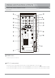
Optical Fiber Camera Adaptor LS-700
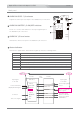
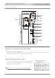
Rear panel
Input the HD-Y component video signal or the composite video signal from a camera.
PROMPTER/REF.VIDEO OUT connector (BNC)
Outputs the HD-Y component or composite video signal input to the PROMPTER/REF. VIDEO IN
connector of the Base Station.
HD-Y/VIDEO IN connector (BNC)
Input the audio signal from a microphone, or a camera, etc.
SMPTE optical fiber cable connector and Cap
AUDIO IN 1/2 connectors (XLR 3-pin, female)
RET 1/2 HD-Y/VIDEO OUT connector (BNC)
Outputs the HD-Y component return video signal or the composite return video signal input to the
HD-Y/VIDEO RET 1 IN or HD-Y/VIDEO RET 2 IN connector of the Base Station LS-800.
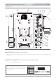
Selects the output signal from the RET 1 IN or RET 2 IN connector by the RET 1/2 select switch( )
onthe main panel.
Connect to the Base Station LS-800 with an optical fiber cable.
Be sure to put the cap on the SMPTE optical fiber cable connector when the optical fiber cable isnt
connected.
TALLY OUT connector (BNC)
Outputs the Red and Green TALLY signals input to the TALLY IN connector of the Base Station LS-800.
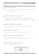
TALLY signal Red : 5V
Green : 3V
OFF : 0V
Pin assignment XLR 3-pin, female
1PIN : GND
2PIN : HOT
3PIN : COLD