
Instruction User Manual
43
Adjustments and Settings for LS-700
2
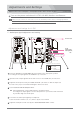
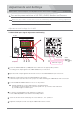
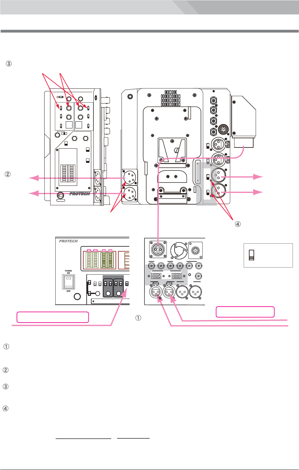
PGM AUDIO output signal monitoring and Setting
PGM AUDIO
OUT 1/2
LINE/MIC select switch
PRONPTER/
REF.VIDEO
OUT
RET1/2
HD-Y/
VIDEO
OUT
HD-Y/
VIDEO
IN
LINE
P48
MIC
LINE
MIC
LINE
MIC
AUDIO
IN 1
LINE
P48
MIC
AUDIO
IN 2
PGM AUDIO
OUT 1
PGM AUDIO
OUT 2
TALLY
OUT
REMOTE
(rear panel)
P
4
8
I
O
I
O
to
camcorder
LINE
MIC
LINE : +4dB
MIC : -60dB
HEADSET 1/2
HEADSET
DL-400
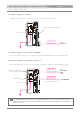
Set the PGM AUDIO OUT 1/2 LINE/MIC select switch to the
appropriate position according to the rated input level of the
equipment connected to the PGM AUDIO OUT 1/2 connectors.
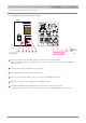
Put on a intercom headset DL-400
Input a PGM audio signal to the PGM AUDIO IN 1/2 connector of LS-800
or turn on the 1 kHz ON/OFF switch of LS-800.
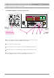
(main panel)
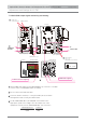
Select the monitor channel, 1 or 2 by the PGM 1/2 select switch
and adjust the audio level by the PGM volume.
LINE
LINE
MIC
MIC
MIC
CA AUDIO
1
PGM AUDIO IN
OFF
ON
1kHz
LMT
MIC
LMT
2
1
ST
CA
PGM
MONI
OUT
MONI.VOL
PGM INPUT
MONI
OVER
OVER OVER OVER
CABLE
CONNECTOR
CA AUDIO
2
(front panel)
LANC
TALLY
OPT
HD/SDI OUT 1
IN OUT
HD-Y/VIDEO
OUT
HD/SDI IN1
HD/SDI
RET
12 1
2
AUDIO IN
CA
AUDIO OUT
PGM
(rear panel)
LS-700
LS-800
PGM audio signal
1 kHz reference signal
Rated input level Position
+ 4 dB LINE
- 60dB MIC
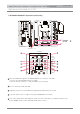
Optical Fiber Camera Adaptor LS-700/Optical Fiber Base Station LS-800
LS-700/LS-800
H.P
INCOM
1
2
12
AUDIO IN
MONITOR
LEVEL
AUDIO IN
LEVEL
AUDIO IN
12
OFF
ON
ON
AUDIO IN
LIMITER
OFF
OVER OVER
HD-SDI
REMOTE
REF
RET
SYSTEM
TALLY
ON
POWER
OFF
HEADSET1 ▶
HEADSET2 ▶
OPTICAL FIBER CAMERA ADAPTOR
TALLY
INCOM
PGM
TALK
ENG
PROD
PGMPGM
PGM
RET
2
1
OFF
ON
2
1
3
2
1kHz
OFF
ON
1/2
TALK
ENG
PROD
2
1
OFF
ON
12
TC
SIDE TONE
PGM 1/2
select switch
PGM volume