
Instruction User Manual

27
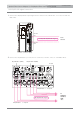
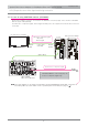
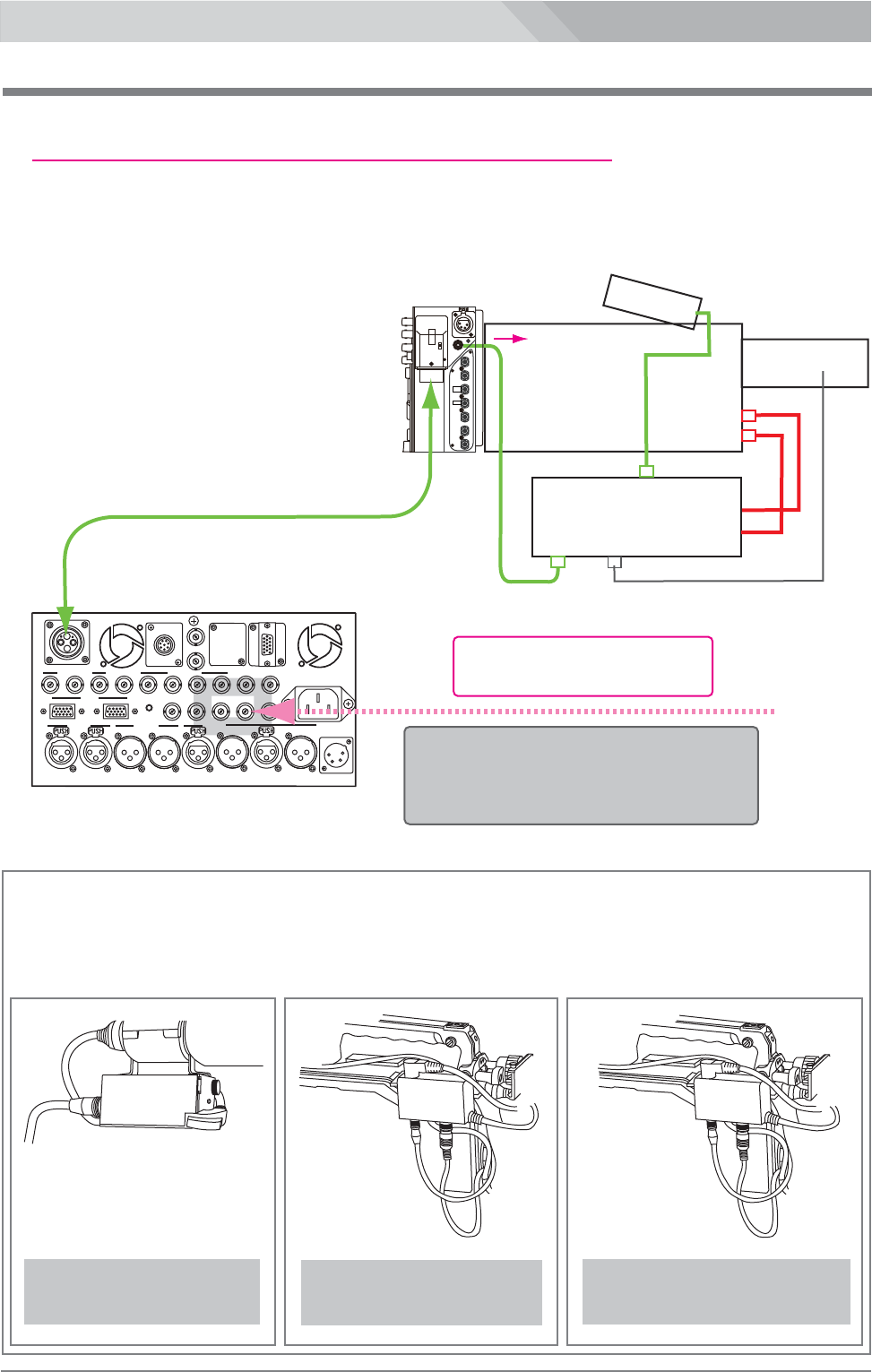
HD-Y/Composite return video signal monitoring connection
Optical Fiber Camera Adaptor LS-700/Optical Fiber Base Station LS-800
LS-700/LS-800
2-3
Using VF Interface Unit VIF-100/BC/P, connect the IF OUT connector of LS-700 to the 6-pin connector of
VIF-100/BC/P with the 6-pin cable (VC-450).
In case of using the viewfinder to display the return signal :
VF
LENS
Camera
VF
LENS
CAM VF
CAM LENS
LENS
VF
RET
IN
( 6-pin cable )
RETURN
signal
IF OUT
RET
HD-SDI
OUT2
HD-SDI
IN2
REF.
OUT
HD-SDI
IN1
RET
HD-SDI
OUT1
LANC
TC
IN
TC
OUT
DC OUT 15V (MAX3A)
▲
OFF
H
L
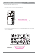
LS-700
VIF-100/-100BC/-100P
PROTECH
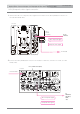
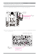
VIF-100
( for SONY )
VIF-100P
( for Panasonic )
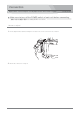
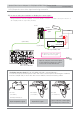
Vierfinder Interface Unit(VIF-100, VIF-100BC, VIF-100P, optional) fitting up :
Loosen the screw of the microphone holder and remove the microphone. And hang the Viewfinder
Interface Unit(VIF-100) on the holder and connect with CA, camera, and lens by cables.
PROTECH
VIF-100BC
( for SONY )
PDW-355, PDW-335, etc.
Input composite signal
Input HD-Y signal
Input composite or HD-Y signal
according to the camera used
AC IN
100/200V(85-240V)
LANC
TALLY
OPT
REF. INHD/SDI OUT 1
PROMPTER/
IN
OUT
VIDEO OUT
HD-Y/VIDEO
OUT
RET1 IN
TC IN
TC OUT
REMOTE
HD/SDI IN1
HD/SDI OUT 2
HD-Y/VIDEO
REF.
VIDEO IN
RET2 IN
HD-Y/VIDEO
HD/SDI IN2
RET RET
INTERCOM
12 1
2
MADE IN JAPAN
AUDIO IN
CA
AUDIO OUT
DC IN
12V(12V-18V)
PGM
2W PROD
2W ENG
INTERCOM
4W
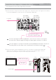
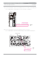
LS-800
HD-Y/VIDEO
RET
1 IN or RET
2 IN
from
switcher,
etc.
Composite return video signal
or HD-Y return video signal
Input the composite return video signal
or HD-Y signal according to the camera
connected to LS-700 and VIF-100.
( OPT cable )