
Instruction User Manual
LS-800
18
Optical Fiber Base Station LS-800
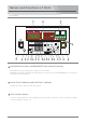
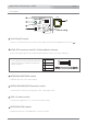
Rear panel
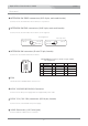
REMOTE connector (8-pin or 10-pin)
Connect to the remote controller.
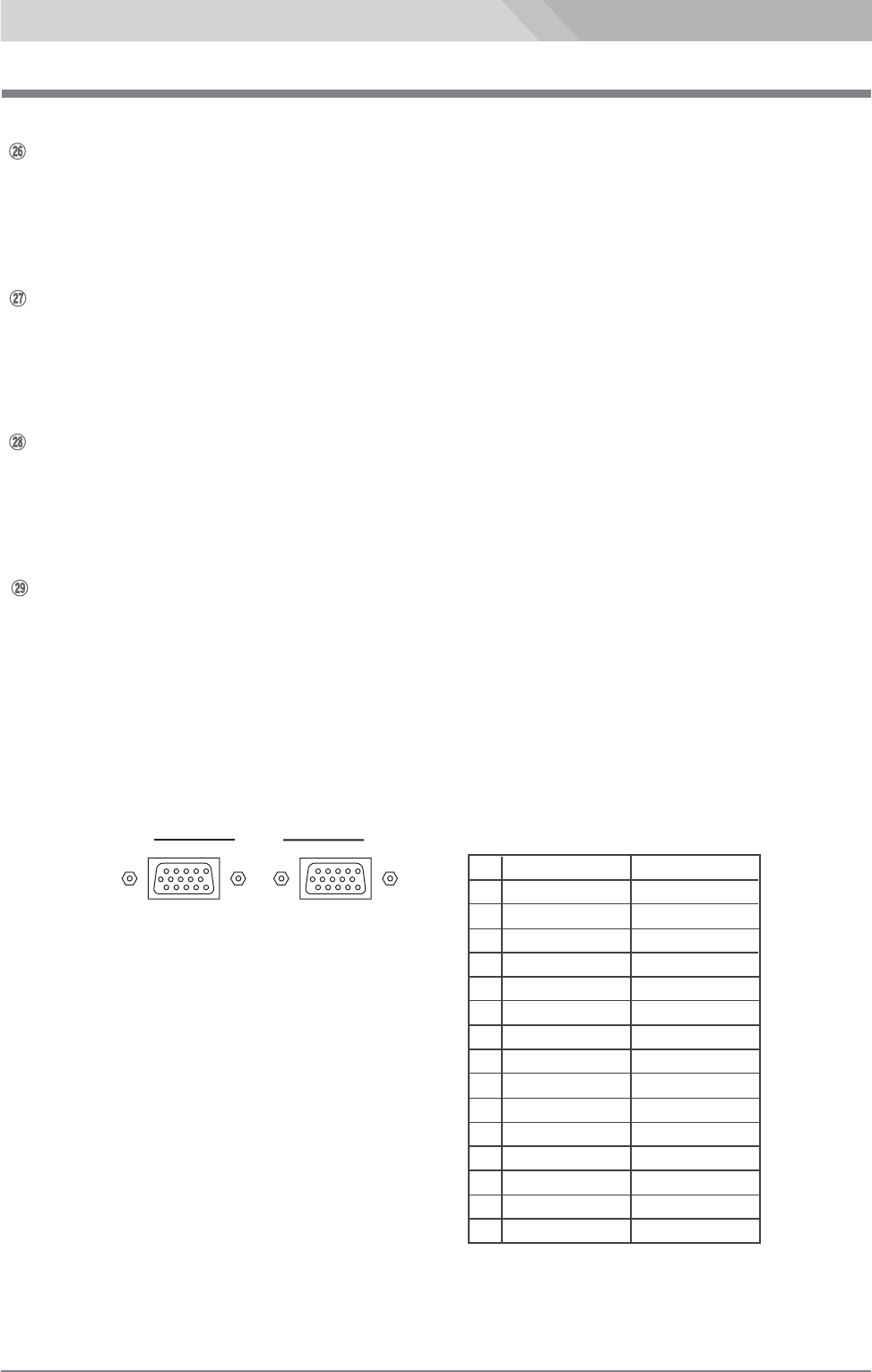
TALLY IN and OUT connectors (HD D-sub 15-pin)
Input the tally signals from a switcher. And outputs the tally signals to the TALLY IN connector.
For the multi-camera operation, connect the TALLY OUT connector to the TALLY IN connector of the
next base station.
Select the tally channel by the TALLY select switch,1 to 5, on the front panel.
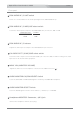
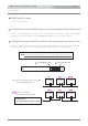
Input a time code signal. And outputs the time code signal from LS-700.
TC IN and TC OUT connectors (BNC)
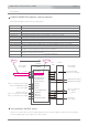
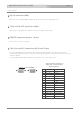
No. Signal Color
1
RED TALLY 1 BLACK
2 RED TALLY 2 BROWN
3 RED TALLY 3 RED
4 RED TALLY 4 ORANGE
5 RED TALLY 5 YELLOW
6 GREEN
7 BLUE
8 PURPLE
9 GRAY
10 COM(GND) WHITE
11 GREEN TALLY 1 PINK
12 GREEN TALLY 2 LIGHT GREEN
13 GREEN TALLY 3 BLACK/WHITE
14 GREEN TALLY 4 BROWN/WHITE
15 GREEN TALLY 5 RED/WHITE
TALLY IN/OUT Connectors
(HD D-sub 15-pin, female)
Pin Assignment
TALLY
IN OUT
Input the reference(GENLOCK) signal from an external reference signal generator.
REF. IN connector (BNC)