TM Optical Fiber Cable Studio System LS-700/LS-800 Operating I nstructions Before operating the system, please read this manual thoroughly and remain it for future reference. Volume1.0, 1st edition Ver.1.
:$51,1* 7R UHGXFH WKH ULVN RI ILUH RU HOHFWULF VKRFN GR QRW H[SRVH WKLV DSSDUDWXV WR UDLQ RU PRLVWXUH )RU WKH FXVWRPHUV LQ WKH 8 6 $ 7KLV HTXLSPHQW KDV EHHQ WHVWHG DQG IRXQG WR FRPSO\ ZLWK WKH OLPLWV IRU D &ODVV $ GLJLWDO GHYLFH SXUVXDQW WR 3DUW RI WKH )&& 5XOHV 7KHVH OLPLWV DUH GHVLJQHG WR SURYLGH UHDVRQDEOH SURWHFWLRQ DJDLQVW KDUPIXO LQWHUIHUHQFH ZKHQ WKH HTXLSPHQW LV RSHUDWHGLQ D FRPPHUFLDO HQYLURQPHQW 7KLV HTXLSPHQW JHQHUDWHV XVHV DQG FDQ UDGLDWH UDGLR IUHTXHQF\ HQHUJ\ DQG LI Q
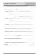
Table of contents Optical Fiber Camera Adaptor LS-700/Optical Fiber Base Station LS-800 Names and Functions of Parts LS-700 LS-800 LS-700/LS-800 4 Main panel 4 Rear panel 7 Side connector panel 10 Front panel 12 Rear panel 17 Connection 21 Adjustments and Settings 42 Supplied Accessories 49 System Connection Guide 50 Multi-Camera System Connection Guide 51 Outside View and Dimensions / Specifications 52 LS-700 52 LS-800 54 03
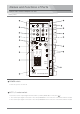
Names and Functions of Parts LS-700 Optical Fiber Camera Adaptor LS-700 Main panel SIDE TONE RET 2 1 H.P PGM PGM PGM PGM 1 1 2 2 PROD PROD INCOM INCOM ENG ENG 2 ON TALK OFF 1 3 2 1 1/2 AUDIO MONITOR LEVEL ON TALK OFF AUDIO IN LEVEL 2 ON AUDIO IN LIMITER ON 1kHz OFF 1 TALLY TALLY OFF SYSTEM REMOTE HD-SDI REF RET TC OVER OVER ON 2 OFF HEADSET1 HEADSET2 2 1 AUDIO IN OFF ON POWER OPTICAL FIBER CAMERA ADAPTOR POWER switch Turns the power on and off.
Optical Fiber Camera Adaptor LS-700 LS-700 Main panel INTERCOM HEADSET 1 PGM 1/2 select switch and PGM volume Selects the PGM audio channel, 1 or 2 to monitor the audio by the INTERCOM HEADSET 1. And adjusts the audio level. INTERCOM HEADSET 2 PGM 1/2 select switch and PGM volume Selects the PGM audio channel, 1 or 2 to monitor the audio by the INTERCOM HEADSET 2. And adjusts the audio level.
Optical Fiber Camera Adaptor LS-700 LS-700 Main panel AUDIO IN LEVEL 1/2 volumes 1 2 1 1/2 Adjusts the audio input level input to the AUDIO IN 1/2 connectors. AUDIO MONITOR LEVEL AUDIO IN LEVEL 2 ON AUDIO IN LIMITER ON 1kHz OFF 1 TALLY TALLY SYSTEM REMOTE HD-SDI REF RET TC OFF AUDIO IN LIMITER 1/2 ON/OFF switches Turns on or off the audio limiters for the input signals input to the AUDIO IN 1/2 connectors.
Optical Fiber Camera Adaptor LS-700 LS-700 Rear panel TALLY OUT RET1/2 HD-Y/ VIDEO OUT PRONPTER/ REF.VIDEO OUT HD-Y/ VIDEO IN REMOTE AUDIO IN 1 LINE MIC P48 AUDIO IN 2 LINE MIC P48 PGM AUDIO OUT 1 LINE MIC PGM AUDIO OUT 2 LINE MIC HEADPHONE connector, (φ3.5 Jack) Connect a headphone with φ3.5 connector to monitor the audio signal connected to the AUDIO IN 1/2 connectors. INTERCOM HEADSET 1/2 connectors (XLR 4-pin, male) Connect the INTERCOM HEADSET.
Optical Fiber Camera Adaptor LS-700 LS-700 Rear panel TALLY OUT connector (BNC) Outputs the Red and Green TALLY signals input to the TALLY IN connector of the Base Station LS-800. TALLY signal Red : 5V Green : 3V OFF : 0V RET 1/2 HD-Y/VIDEO OUT connector (BNC) Outputs the HD-Y component return video signal or the composite return video signal input to the HD-Y/VIDEO RET 1 IN or HD-Y/VIDEO RET 2 IN connector of the Base Station LS-800.
Optical Fiber Camera Adaptor LS-700 LS-700 Rear panel AUDIO IN 1/2 LINE/MIC/P48 select switch Selects the input signal level, LINE, MIC or P48, according to the signal level input to the AUDIO IN 1/2 connectors. LINE : When a line-level ( +4 dB ) signal source is connected. MIC : When a microphone ( -60 dB ) is connected. P48 : When a phantom microphone ( -60 dB ) which requires DC +48V power is connected.
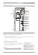
Optical Fiber Camera Adaptor LS-700 LS-700 Side connector panel DC OUT 15V (MAX3A) ▲ H L LANC OFF IF OUT RET HD-SDI OUT1 HD-SDI IN1 RET HD-SDI OUT2 HD-SDI IN2 REF. OUT TC IN TC OUT DC OUT 15V connector (XLR 4-pin, female) Outputs the DC 15V power(MAX 3A). Maximum output power is 75W in total of the power from the DC consumption by a camcorder from the V-shoe battery adaptor.
Optical Fiber Camera Adaptor LS-700 LS-700 Side connector panel RET HD-SDI OUT 1 Connector (BNC) Outputs the return 3G/HD/SD-SDI signal connected to the RET HD/SDI IN 1 connector of the Base Station LS-800. HD-SDI IN 1 Connector (BNC) Input the 3G/HD/SD-SDI signal from a camera. RET HD-SDI OUT 2 Connector (BNC) Outputs the return 3G/HD/SD-SDI signal connected to the RET HD/SDI IN 2 connector of the Base Station LS-800. HD-SDI IN 2 Connector (BNC) Input the 3G/HD/SD-SDI signal from a camera.
Names and Functions of Parts Optical Fiber Base Station LS-800 LS-800 Front panel OPTICAL FIBER BASE STATION CA AUDIO OVER PGM INPUT OVER OVER OVER CABLE CONNECTOR MONI 1 MIC HD-SDI IN 1 HD-SDI IN 2 PROMPTER IN HD-SDI 0UT 1 HD-SDI 0UT 2 RET IN REF.
Optical Fiber Base Station LS-800 LS-800 Front panel CABLE CONNECTOR Indicator (Status indicator) Each indicator lights up under the following states. Indication SYSTEM HD-SDI IN1 HD-SDI IN2 PROMPTER IN HD-SDI OUT 1 HD-SDI OUT 2 RET IN REF. IN TC IN HD-Y/VIDEO OUT REMOTE RET IN 1 RET IN 2 REMOTE VIDEO STATUS Power is turned on and the system is operating. 3G/HD/SD-SDI signal is input to the RET HD-SDI IN 1 connector of LS-800. 3G/HD/SD-SDI signal is input to the RET HD-SDI IN 2 connector of LS-800.
Optical Fiber Base Station LS-800 LS-800 Front panel PGM AUDIO IN 1/2 LMT switch Turns on or off the limiter for the audio input signal of the PGM AUDIO IN 1/2. PGM AUDIO IN 1/2 MIC/LINE select switch Selects the audio input level input to the PGM AUDIO IN 1/2 connector, MIC or LINE. Rated input level - 60dB + 4 dB Position MIC LINE PGM AUDIO IN 1/2 volume Adjusts the audio input level input to the PGM AUDIO IN 1/2 connector.
Optical Fiber Base Station LS-800 LS-800 Front panel TALK INTERCOM PGM SIDETONE PROD ENG HEAD SET PGM 1 HP.VOL 2 TALK ON/OFF switch Turns on or off the microphone of a intercom headset connected to the HEAD SET connector ( HEAD SET connector and HP. VOL(headphone volume) Connect the supplied intercom headset DL-400. Adjust the audio level of the headphone. In case using the headset with the XLR 4-pin male connector, prepare the cable with the XLR 4-pin female connectors.
Optical Fiber Base Station LS-800 LS-800 Front panel POWER ON/OFF switch Turns on or off the power. Termination resistance ON/OFF switch for intercom producer line (under cover) Turns on or off the termination resistance for the intercom 2W producer line according to the equipment of the intercom system connected to the INTERCOM 2W PROD connectors on the rear panel.
Optical Fiber Base Station LS-800 LS-800 Rear panel OPT INTERCOM 4W TC IN TC OUT RET HD/SDI IN1 HD/SDI OUT 1 RET HD/SDI IN2 HD/SDI OUT 2 REF. IN AC IN 100/200V(85-240V) TALLY IN LANC OUT REMOTE VIDEO OUT CA AUDIO OUT PGM AUDIO IN 1 HD-Y/VIDEO OUT 2 1 HD-Y/VIDEO RET1 IN HD-Y/VIDEO PROMPTER/ REF.
Optical Fiber Base Station LS-800 LS-800 Rear panel REF. IN connector (BNC) Input the reference(GENLOCK) signal from an external reference signal generator. TC IN and TC OUT connectors (BNC) Input a time code signal. And outputs the time code signal from LS-700. REMOTE connector (8-pin or 10-pin) Connect to the remote controller. TALLY IN and OUT connectors (HD D-sub 15-pin) Input the tally signals from a switcher. And outputs the tally signals to the TALLY IN connector.
Optical Fiber Base Station LS-800 LS-800 Rear panel TALLY IN LANC OUT REMOTE VIDEO OUT CA AUDIO OUT PGM AUDIO IN 1 HD-Y/VIDEO OUT 2 1 HD-Y/VIDEO RET1 IN HD-Y/VIDEO PROMPTER/ REF.VIDEO IN RET2 IN INTERCOM DC IN 12V(12V-18V) 2 2W PROD MADE IN JAPAN 2W ENG HD-Y/VIDEO OUT connector (BNC) Outputs the HD-Y or compoosite video signal from LS-700. REMOTE VIDEO OUT connector (BNC) Outputs the composite video signal input to LS-700 from a camera via the 8-pin remote control cable.
Optical Fiber Base Station LS-800 LS-800 Rear panel INTERCOM 2W PROD connectors (XLR 3-pin, male and female) Connect to an external 2-wire intercom line for a producer. INTERCOM 2W ENG connectors (XLR 3-pin, male and female) Connect to an external 2-wire intercom line for an engineer. Pin assignment XLR 3-pin, female 2PIN : NC 1PIN : GND XLR 3-pin, male 1PIN : GND 3PIN : SIGNAL 2PIN : NC 3PIN : SIGNAL INTERCOM 4W connector (D-sub 15-pin, female) Connect to an external 4-wire intercom line.
Connection Optical Fiber Camera Adaptor LS-700/Optical Fiber Base Station LS-800 LS-700/LS-800 Make sure to turn off the POWER switch of each unit before connecting. 接続する前に各機器の電源スイッチは必ずOFFにしてください。 Mount on tripod 1 Fix the Optical Fiber Camera Adaptor LS-700 to the V-shoe mount of the camera. 2 Mount the camera on a tripod.
Optical Fiber Camera Adaptor LS-700/Optical Fiber Base Station LS-800 LS-700/LS-800 HD-SDI/SD-SDI signal connection 1 Connect the 3G/HD/SD-SDI output signal from a camera to the HD-SDI IN 1 or 2 connector with the BNC cable. DC OUT 15V (MAX3A) ▲ H L LANC OFF IF OUT HD-SDI IN 1 RET HD-SDI OUT1 HD-SDI IN1 RET HD-SDI OUT2 3G-SDI/HD-SDI/SD-SDI signal from camera HD-SDI IN2 HD-SDI IN 2 REF.
Optical Fiber Camera Adaptor LS-700/Optical Fiber Base Station LS-800 LS-700/LS-800 HD/SD-SDI return signal monitoring connection 1 Connect the RET HD-SDI OUT 1 or 2 connector of LS-700 to the SDI(HD/SD) input connector of a HD/SD-SDI monitor with a BNC cable. DC OUT 15V (MAX3A) ▲ HD/SD-SDI monitor H L RET HD-SDI OUT 1 LANC OFF IF OUT SDI(HD/SD) IN RET HD-SDI OUT1 3G/HD/SD-SDI signal HD-SDI IN1 or RET HD-SDI OUT2 RET HD-SDI OUT 2 HD-SDI IN2 REF.
Optical Fiber Camera Adaptor LS-700/Optical Fiber Base Station LS-800 LS-700/LS-800 HD-Y/Composite video signal connection 1 Connect the HD-Y or composite video signal from a camera to the HD-Y/VIDEO IN connector of LS-700 with a BNC cable. LS-700 TALLY OUT RET1/2 HD-Y/ VIDEO OUT HD-Y/ VIDEO IN (BNC) PRONPTER// REF.
Optical Fiber Camera Adaptor LS-700/Optical Fiber Base Station LS-800 LS-700/LS-800 HD-Y/Composite return video signal input connection 1 Connect the HD-Y component return video signal or the composite return video signal from a switcher to the HD-Y/VIDEO RET 1/2 IN connectors of LS-800 with a BNC cable. HD-Y/VIDEO RET 1 IN (BNC) HD-Y/VIDEO RET 2 IN (BNC) LS-800 to LS-700 INTERCOM 4W OPT TC IN TC OUT RET HD/SDI IN1 HD/SDI OUT 1 RET HD/SDI IN2 HD/SDI OUT 2 REF.
Optical Fiber Camera Adaptor LS-700/Optical Fiber Base Station LS-800 LS-700/LS-800 HD-Y/Composite return video signal monitoring connection 2-2 In case of using PROTECH monitor (LVM-89W) : Connect the IF OUT connector of LS-700 to the MONI IF connector(6-pin) of the monitor LVM-89W with the 6-pin cable(VC-450). The RET video composite signal, TALLY signal and DC power are supplied from the IF OUT connector of LS-700.
Optical Fiber Camera Adaptor LS-700/Optical Fiber Base Station LS-800 LS-700/LS-800 HD-Y/Composite return video signal monitoring connection 2-3 In case of using the viewfinder to display the return signal : Using VF Interface Unit VIF-100/BC/P, connect the IF OUT connector of LS-700 to the 6-pin connector of VIF-100/BC/P with the 6-pin cable (VC-450).
Optical Fiber Camera Adaptor LS-700/Optical Fiber Base Station LS-800 LS-700/LS-800 Reference (GENLOCK) signal connection 1 Connect the REF. OUT connector to a camera with a BNC cable. DC OUT 15V (MAX3A) ▲ H L LANC OFF IF OUT RET HD-SDI OUT1 HD-SDI IN1 RET HD-SDI OUT2 REF. OUT (BNC) HD-SDI IN2 Reference (GENLOCK) signal to camera REF. OUT TC IN TC OUT LS-700 2 (connector panel) Connect a reference (GENLOCK) signal from an reference (GENLOCK) signal generator to the REF.
Optical Fiber Camera Adaptor LS-700/Optical Fiber Base Station LS-800 LS-700/LS-800 接続方法 Time code signal connection 1 TC 信号の接続 Connect the TC IN/TC OUT connectors to the TC OUT/IN connectors of a camera, etc. with a BNC cable. タイムコードを使用する場合は、LS-700のTC IN/OUTコネクタからカメラ等へBNCケーブルで接続します。 LS-700 DC OUT 15V (MAX3A) ▲ H L LANC OFF IF OUT RET HD-SDI OUT1 HD-SDI IN1 RET HD-SDI OUT2 HD-SDI IN2 REF. OUT Time code signal TC IN (BNC) TC IN camera, etc.
Optical Fiber Camera Adaptor LS-700/Optical Fiber Base Station LS-800 LS-700/LS-800 PROMPTER/REF.VIDEO signal (composite) connection 1 Connect the PROMPTER/REF. VIDEO OUT connector to a prompter with a BNC cable. LS-700 PROMPTER/ REF. VIDEO OUT (BNC) TALLY OUT RET1/2 HD-Y/ VIDEO OUT to prompter, etc. PRONPTER/ REF.
Optical Fiber Camera Adaptor LS-700/Optical Fiber Base Station LS-800 LS-700/LS-800 PROMPTER VIDEO signal (3G/HD/SD-SDI) connection NOTE : In case of using the prompter with the 3G/HD/SD-SDI input, connect the RET HD-SDI OUT 2 connector of LS-700 to a promptor and connect the 3G/HD/SD-SDI signal from an external video camera, etc. to the RET HD/SDI IN 2 connector of LS-800. 1 Connect the RET HD-SDI OUT2 connector to a prompter with a BNC cable.
Optical Fiber Camera Adaptor LS-700/Optical Fiber Base Station LS-800 LS-700/LS-800 CA AUDIO signal connection 1 Connect the audio output signal from a camera to the AUDIO IN 1/2 connector with a XLR 3-pin cable. headphone H.P TALLY OUT φ3.5 jack for monitoring the AUDIO IN signal RET1/2 HD-Y/ VIDEO OUT PRONPTER/ REF.
Optical Fiber Camera Adaptor LS-700/Optical Fiber Base Station LS-800 LS-700/LS-800 PGM AUDIO signal connection 1 Connect the audio signal from a switcher, an audio mixer, etc. to the PGM AUDIO IN 1/2 connectors with XLR 3-pin cables. (rear panel) LS-800 (front panel) INTERCOM 4W OPT TC IN TC OUT headphone RET HD/SDI IN1 HD/SDI OUT 1 RET HD/SDI IN2 HD/SDI OUT 2 REF.
Optical Fiber Camera Adaptor LS-700/Optical Fiber Base Station LS-800 LS-700/LS-800 INTERCOM HEADSET connection 1 (LS-700) Connect the supplied Intercom headset DL-400 to the INTERCOM HEADSET 1/2 connector. RET SIDE TONE 2 1 H.
Optical Fiber Camera Adaptor LS-700/Optical Fiber Base Station LS-800 LS-700/LS-800 INTERCOM line connection 1 To communicate with an external intercom 4-wire system, connect the INTERCOM 4W connector to an external intercom 4-wire line with a HD D-sub 15-pin cable. to INTERCOM Station, etc. INTERCOM 4W line INTERCOM 4W (HD D-sub 15-pin) LS-800 INTERCOM 4W Connector (HD D-sub 15-pin, female) Pin Assignment INTERCOM 4W OPT TC IN No.
Optical Fiber Camera Adaptor LS-700/Optical Fiber Base Station LS-800 LS-700/LS-800 TALLY signal connection 1 Connect the TALLY OUT connector of LS-700 to a monitor, etc. with a BNC cable. TALLY OUT (BNC) TALLY OUT to monitor, etc. TALLY signal RET1/2 HD-Y/ VIDEO OUT PRONPTER/ REF.
Optical Fiber Camera Adaptor LS-700/Optical Fiber Base Station LS-800 LS-700/LS-800 REMOTE Controller connection 1 Connect the REMOTE connector of LS-700 to the remote connector of a camera with the supplied remote cable(RCC-450S/P). When using the LANC REMOTE, connect the LANC connector with the camera. to camera Remote cable (RCC-450S/P) LANC (φ 2.5) DC OUT 15V (MAX3A) to camera REMOTE (8-pin or 10-pin) ▲ TALLY OUT RET1/2 HD-Y/ VIDEO OUT H L LANC PRONPTER/ REF.
Optical Fiber Camera Adaptor LS-700/Optical Fiber Base Station LS-800 LS-700/LS-800 REMOTE Controller connection In case of using a camera which can output the video composite signal via the remote cable, the composite video signal can be output from the REMOTE VIDEO OUT connector of LS-800. REMOTE (8-pin or 10-pin) TALLY OUT RET1/2 HD-Y/ VIDEO OUT Remote cable (RCC-450S/P) PRONPTER/ REF.
Optical Fiber Camera Adaptor LS-700/Optical Fiber Base Station LS-800 Optical Fiber Cable connection 1 Connect both the OPT connectors of LS-700 and LS-800 with an optical fiber cable. TALLY OUT RET1/2 HD-Y/ VIDEO OUT OPT connector PRONPTER/ REF.
Optical Fiber Camera Adaptor LS-700/Optical Fiber Base Station LS-800 LS-700/LS-800 Power Supply connection 1 DC power supply to LS-700 The DC power to LS-700 is supplied from the Optical Fiber Base Station LS-800 via the optical fiber cable. Connect both the OPT connectors of LS-700 and LS-800 with an optical fiber cable. And connect the AC IN 100/200V(85-240V) connector to the AC outlet with the supplied AC power cable. TALLY OUT RET1/2 HD-Y/ VIDEO OUT OPT connector PRONPTER/ REF.
Optical Fiber Camera Adaptor LS-700/Optical Fiber Base Station LS-800 LS-700/LS-800 Power Supply connection 2 DC power supply to a camera The DC power is supplied to a camera via the V-shoe mount (battery adaptor). DC OUT 15V (MAX3A) ▲ H L LANC V-shoe mount (battery adaptor) OFF IF OUT RET HD-SDI OUT1 OPT connector HD-SDI IN1 RET HD-SDI OUT2 HD-SDI IN2 REF.
Adjustments and Settings Optical Fiber Camera Adaptor LS-700/Optical Fiber Base Station LS-800 LS-700/LS-800 Turn on the power switches of LS-700, LS-800, Monitor and Camera. Make sure the volume of each unit is set to the minimum position before starting adjustment. Never turn up the volumes suddenly to prevent hearing impairment. Adjustments and Settings for LS-700 1 Audio input signal adjustment and setting (main panel) RET HEADPHONE SIDE TONE 2 1 H.
Optical Fiber Camera Adaptor LS-700/Optical Fiber Base Station LS-800 LS-700/LS-800 Adjustments and Settings for LS-700 2 PGM AUDIO output signal monitoring and Setting PGM 1/2 select switch PGM volume LS-700 RET SIDE TONE 2 1 H.P TALLY OUT PGM PGM PGM PGM 1 1 RET1/2 HD-Y/ VIDEO OUT 2 2 PROD INCOM PROD INCOM ENG ENG 2 ON TALK OFF 1 3 2 1 1/2 AUDIO IN MONITOR LEVEL PRONPTER/ REF.
Optical Fiber Camera Adaptor LS-700/Optical Fiber Base Station LS-800 LS-700/LS-800 Adjustments and Settings for LS-700 3 INTERCOM HEADSET adjustment and Setting RET SIDE TONE 2 1 H.P TALLY OUT PGM PGM PGM PGM 1 1 RET1/2 HD-Y/ VIDEO OUT 2 2 PROD INCOM PROD INCOM ENG ENG 2 ON TALK OFF 1 3 2 1 1/2 AUDIO IN MONITOR LEVEL PRONPTER/ REF.
Adjustments and Settings Optical Fiber Camera Adaptor LS-700/Optical Fiber Base Station LS-800 LS-700/LS-800 Turn on the power switches of LS-700, LS-800, Monitor and Camera. Make sure the volume of each unit is set to the minimum position before starting adjustment. Never turn up the volumes suddenly to prevent hearing impairment.
Optical Fiber Camera Adaptor LS-700/Optical Fiber Base Station LS-800 LS-700/LS-800 Adjustments and Settings for LS-800 2 CA audio signal monitoring and setting LS-800 OPT CA AUDIO OVER OVER RET HD/SDI IN1 HD/SDI OUT 1 TALLY IN MONI 1 MONI CA AUDIO OUT PGM AUDIO IN MIC LINE LINE MONI.VOL PGM 1 MONI headphone connector (φ 6.3) HD-Y/VIDEO OUT CA AUDIO OUT MIC 2 LANC OUT ST CA HD/SDI (front panel) 2 1 2 (rear panel) CA audio signal HEADPHONE to switcher, audio mixer, VTR, etc.
Optical Fiber Camera Adaptor LS-700/Optical Fiber Base Station LS-800 LS-700/LS-800 Adjustments and Settings for LS-800 2 INTERCOM HEADSET adjustment and Setting OPT OPTICAL FIBER BASE STATION CA AUDIO OVER PGM INPUT OVER OVER OVER CABLE CONNECTOR RET HD/SDI IN1 HD/SDI OUT 1 TALLY IN HD/SDI LANC OUT MONI 1 MONI from switcher, audio mixer, etc. 1 HD-SDI IN 2 HD-SDI 0UT 2 VIDEO IN REF.
Optical Fiber Camera Adaptor LS-700/Optical Fiber Base Station LS-800 LS-700/LS-800 Adjustments and Settings for LS-800 4 TALLY indicator Setting Select the TALLY channel and set the TALLY channel select switch to the ON position to light up the tally indicator. Make sure that the TALLY indicator lights up when the corresponding tally channel of a switcher is selected.
Supplied Accessories LS-700 / LS-800 LS-700/LS-800 Optical Fiber Camera Adaptor LS-700 Description Model name Remote Cable RCC-450S or RCC-450P Quantity 1 1 Operating Instructions(CD-ROM) Optical Fiber Base Station LS-800 Model name Description Quantity AC Cable 1 Operating Instructions(CD-ROM) 1 49
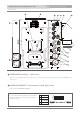
System Connection Guide LS-700/LS-800 Optical Fiber Studio System CLASS 1 LASER PRODUCT LS-700/LS-800 OPTICAL FIBER STUDIO SYSTEM System Connection Guide 8.
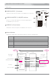
Multi-Camera System Connection Guide LS-700/LS-800 Optical Fiber Studio System LS-700/LS-800 OPTICAL FIBER STUDIO SYSTEM CLASS 1 LASER PRODUCT Multi-Camera System Connection Guide ●Camera 1 Tally/RET HD-SDI/Genlock ●Monitor HDF-700(option) HD-SDI/RET HD-SDI/Tally/DC Power ●Zoom lens remote control cable ●Zoom remote controller extention cable RET IN ●BNC cable TALLY IN 1 ●BNC cable DC IN RETURN MAIN Switcher ●BNC cable SDI(HD/SD) IN 1 HD-SDI ●DC cable(XLR 4-pin) TALLY OUT ●LS-700 ●Optic
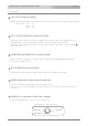
OFF 52 1 ON OFF ON ENG OFF ON OFF HEADSET2 ▶ HEADSET1 ▶ 2 1 AUDIO IN LIMITER ON 2 TALK AUDIO IN LEVEL 3 INCOM 91 OPTICAL FIBER CAMERA ADAPTOR AUDIO IN 2 RET 1 REF TC HD-SDI OVER REMOTE SYSTEM OVER TALLY TALLY OFF 1kHz 2 2 ON 1/2 POWER AUDIO IN MONITOR LEVEL 1 OFF ON ENG INCOM 2 PGM 1 PGM H.
Specifications Optical Fiber Camera Adaptor LS-700 LS-700 Output (RET HD-SDI OUT 1: BNC x1) (RET HD-SDI OUT 2: BNC x1) 3G/HD/SD, Audio,TC embedded 3G/HD/SD, Audio,TC embedded 3G/HD/SD-SDI(return) 2 HD-Y/Composite(return) 1 (BNC x1) : 1Vp-p, 75Ω, Analog composite or HD-Y ※1 Prompter /Ref.
Outside View and Dimensions Optical Fiber Base Station LS-800 LS-800 OPTICAL FIBER BASE STATION PGM INPUT OVER OVER OVER CABLE CONNECTOR MONI 1 MIC HD-SDI IN 1 HD-SDI IN 2 HD-SDI 0UT 1 HD-SDI 0UT 2 RET IN REF.
Specifications Optical Fiber Camera Adaptor LS-800 LS-800 Output 3G/HD/SD-SDI (HD/SDI OUT 1: BNC x3) 2 (HD/SDI OUT 2: BNC x4) 3G/HD/SD, Audio,TC embedded 3G/HD/SD, Audio,TC embedded HD-Y/VIDEO composite 1 (BNC x1) : 1Vp-p, 75Ω, Analog composite or HD-Y Audio (CA audio) 2 (XLR 3-pin(male) x2) : LINE=+4 dB, MIC= -60 dB Time Code 1 (BNC x1) Remote Video 1 (BNC x1) (Composite) Monitor 1 (Stereo headphone jack φ 6.
TM LS-700/LS-800 Operating Instructions