TM Teleprompter HDP-2000 HDP-2000F Operating Instructions Before operating the system, please read this manual thoroughly and remain it for future reference. Volume1, 1st edition Ver.1.
WARNING 安全上の注意 NIPROS accep t n o l i a b i l i t y w h a t e v e r f o r i n c i d e n t a l d a m a g e s a r i s i n g o u t o f t h e u s e or inability to u s e t h e p r o d u c t , i n c l u d i n g , b u t n o t l i m i t e d t o , c o r r u p t i o n o r l o s s o f data, lost busi n e s s r e v e n u e o r s u s p e n s i on o f b u s i n e s s o p e r a t i o n s .
Table of contents Teleprompter HDP-2000/2000F HDP-2000/2000F 目次 Names and Functions of Parts 4 Front panel 4 Left side panel 5 Right side panel 6 Operation panel 8 Rear panel 10 Bottom panel 11 Camera plinth 12 Names and Functions of Parts 13 Fixing 13 Connection 16 Settings 18 Display Setting 18 Camera Setting 19 TALLY Setting 20 Proma Software User s Guide 21 System 30 Outsideview and Dimensions 31 Specifications 32 03
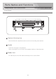
Parts Names and Functions Teleprompter HDP-2000/2000F HDP-2000/2000F 各部名称と働き Front Panel Top board fastening hasp Used to fasten the top board with the mirror and shading cover built-in. Handle Used for carrying the teleprompter. When carrying, be sure to fasten the top board with the fastening hasp. Rubber feet It is able to place the HDP-2000 main body on the desk or floor.
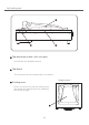
Left side panel Top board lock knobs (left and right) Used to lock the top board opened. Top board The half mirror and the shading cover are installed. Upper panel Shading cover Put the end of the lens into the shading cover and narrow the mouth of it by the drawstring to shut out the light.
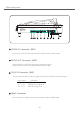
Right side panel TELEPROMPTER HD-SDI IN HD-SDI OUT TALLY HDMI PC IN VBS IN HDP-2000 PB IN POWER OFF ON DC IN 1 GND 4 +12V NIPPON VIDEO SYSTEM CO.,LTD MADE IN JAPAN HD-SDI IN Connector (BNC) Used to input the HD-SDI signal to the prompter with the BNC cable. HD-SDI OUT Connector (BNC) Used to output the HD-SDI signal input to the HD-SDI IN. Connect to the external equipment with the BNC cable.
Right side panel PC IN Connector (HD D-sub 15-pin) Used to input the PC signal to the prompter with the HD D-sub 15-pin cable. VBS IN Connector (BNC) Used to input the composite video signal to the prompter with the BNC cable. PB IN Connector (8ピン) When using the prompter connecting with the PC, used to connect with the PB Remote Controller PB-RM1A or PB-RM1B. Pressing the button of the PB Remote Controller changes the input signal from the PC IN signal to the HD-SDI IN signal.
Operation panel LCD Screen The display screen is 20 inches LCD. MENU / ▲ / ▼ buttons Pressing the the MENU button selects the menu and pressing ▲ / ▼ button adjusts and enters the each setting according to the display on the screen. When Reset is selected, pressing ▲ / ▼ button resets all to standard value(50).
Operation panel RED TALLY OFF/L/H /GREEN TALLY OFF/L/H Switch Set the TALLY indicator, RED TALLY / GREEN TALLY to OFF, L(Low) or H(High). RED TALLY/GREEN TALLY Indicators RED TALLY lights up when the tally signal, the voltage of 4 V to 5 V. GREEN TALLY lights up when the tally signal, the voltage of 2 V to 4 V. PC Switch Used to turn on the display of the PC IN input signal. HD-SDI Switch Used to turn on the display of the HD-SDI IN input signal.
Rear panel Screw holes for the camera plinth fixed Used to fasten the camera plinth to the teleprompter main body. Guide rails for the camera plinth Used to fit the camera plinth to the teleprompter main body. Insert and slide the uniting board of the camera plinth along the groove of the rail until it is in place.
Bottom panel Tripod socket screw hole, female, 1/4 inch. Used to mount the teleprompter alone on the tripod.
Camera plinth Main body uniting board To unite the teleprompter with the camera plinth, this board is inserted in the camera plinth rail. Main body fixing screw The main body of the teleprompter is fixed with this screw. Tripod mounting plate Used to fix the teleprompter to tripod stand. Clamp Used to tighten the plate of tripod. Camera mounting board Used to mount the camera or the tripod base(or tripod adaptor). Clamp Used to tighten the camera mounting board in the appropriate position.
Use Teleprompter HDP-2000/2000F HDP-2000/2000F 使用方法 Fixing 1. When the small size or light weight camera is used, use the balance plate. Install the balance plate to the main body uniting board and the tripod mounting plate by supplieded screws. Caution : Select the appropriate screw holes considering the balance of the weight of the camera and the teleprompter. Tripod mounting plate Main body uniting board Balance plate 2.
Fixing 4. Attach the tripod base to the camera mounting plate of the camera plinth and secure it with the screws. Tripod base (Tripod adaptor) Camera mounting plate 5. Place the teleprompter main body on the main body uniting board of the camera plinth (Put the main body uniting board into the groove of the guide rail on the bottom of the teleprompter main body), and slide it into the depths of the rail until it stops. Main body fixing sarews, left and right 6.
Fixing 7. Mount the camera to the tripod base on the camera plinth. And, loosen the cramps, slide the camera forward or backward until it is in the appropriate position, and tighten the cramps. Caution : The appropriate position is that the top of the lens is in the position a little ahead from the end of the main body. (from 0 cm up to approximately several centimeters) several centimeters HD-SDI IN HD-SDI OUT TALLY HDMI PC IN PB IN VBS IN POWER OFF ON DC IN 1 GND 4 +12V 8.
Connection 1. Connect XLR 4P DC power cable to the DC IN connector on the main body. POWER cable POWER SW DC IN connector 2. Connect the other end of the DC powere cable to the AC adaptor. POWER cable 3. Connect the cables to input and display the signals. Connect the PC IN connector of HDO-2000/F to the PC by the D-sub 15-pin cable. When the HD-SDI play back signal is displayed, input the playback signal to the HD-SDI IN connector by the BNC cable.
Connection 4. Connect the PC IN connector of the main body of the HDP-2000/F to the Proma PC with the supplied HD D-sub 15-pin cable. PC IN connector D-sub 15-pin connector 5. When using the manuscript imaging camera, connect it to the connector of the HDP-2000/F, HDMI connector, VBS IN connector or HD-SDI IN. Manuscript imaging camera HD-SDI HDMI Composite Right side panel TELEPROMPTER HD-SDI IN HD-SDI OUT TALLY HDMI PC IN VBS IN PB IN HDP-2000 NIPPON VIDEO SYSTEM CO.
Setting Teleprompter HDP-2000/2000F HDP-2000/2000F 設定方法 Display 1. After connecting, turn on to supply the power to HDP-2000/F main body, PC and the others and the image is displayed on the screen. According to the input image source, select the INPUT select switch. (NOTE) When using a PC and its software, please operate them according to their instruction manuals. ポータブルスタジオプロンプター はスタジオはもとより機動性を 求められる生中継や報道ニュース をはじめビデオレポート、企業 広報、 テレビ会議など多種多様 な映像コンテンツ製作にために 開発されたプロ映像機器のプロ ンプターです。 2.
Camera Setting 1. Adjusting the camera position by the tripod adjusting so that the camera can image the announcer properly and the announcer can read the manuscript on the screen properly. announcer HD-SDI IN HD-SDI OUT TALLY HDMI PC IN VBS IN PB IN POWER OFF ON DC IN 1 GND 4 +12V manuscript image 2.
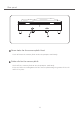
TALLY Setting 1. TALLY Setting : Set the RED TALLY/GREEN TALLY switch to H, L or OFF. TALLY Select Switches RED TALLY GREEN TALLY OFF/L/H OFF/L/H TALLY Indicators RED GREEN PC/PB(HD-SDI) Operation panel Right side panel HD-SDI IN HD-SDI OUT TALLY TELEPROMPTER HDMI PC IN VBS IN HDP-2000 PB IN POWER OFF ON DC IN 1 GND 4 +12V NIPPON VIDEO SYSTEM CO.,LTD MADE IN JAPAN TALLY signal 2. Input the TALLY signal to light on the TALLY indicator of the teleprompter.
Proma Software User's guide PROTECH NIPPON VIDEO SYSTEM CO.
Proma PC begins to push the power supply button. WindowsXP is started when the power supply button of Proma PC is pushed, and the Proma software starts at the same time. Manuscript set making When the Proma software is started for the first time, it is urged like inputting the name of the manuscript set. And, input an arbitrary name . And, click"OK" . 原稿セット名前入力 Input Manuscript set name Click"OK" What is the manuscript set? Please think that it is a file by which it bundles nine manuscript boxes.
Explanation of screen 1. New making of manuscript set 2. Deletion of manuscript set 3 . List of manuscript set CUE 1 CUE 2 CUE CUE 4 CUE 5 CUE 7 CUE 8 CUE CUE 5. Font size 1、New 6. Interlinear 3 6 9 7. Display mode 8. Air-play making of manuscript set:Click this,new manuscript set is made. 2、Deletion 3、List 4. Manuscript box of manuscript set:Displayed manuscript set is deleted. of manuscript set:It is a list of the preserved manuscript set.
Manuscript box making There are nine manuscript boxes in the manuscript set. The manuscript box from 1 of the screens to 9 is clicked. Then, the title and the text input screen appear. And, please input sentences that want to scroll here with Proma. Click "OK" of the lower right of the screen when the input ends.
Set showing Externals when scrolling can be set with the button under a set window. It is safe even if moving to the execution window like an existing setting. Font size Interlinear space Display mode Font size The size of the character is chosen. It becomes easy to look at the character when large size is chosen. And,when the Small size,a lot of characters can be shown. It is adjusted to three size. Interlinear space It adjusts the space of changing line. It is adjusted to three patterns.
The execution window is opened. Before you operates it,confirm it is a direct input mode before it . The execution window is displayed by full-screen when the "ON AIR" button in the lower right of a set window is clicked, and the text written in a set window is displayed. (The ON AR button is clicked.the first manuscript box'is displayed. ) Each manuscript box can be called by pushing nine from keyboard 1. 1 1 The first manuscript box appears when the key to one is pushed.
To return to a set window Click the "BACK" button under the right of the execution window. Click BACK Or, push Returning button of controller. To end Proma Please push the power supply button of Proma PC.
Controller 3 2 1 6 5 7 8 4 9 Font size Interlinear Manuscript box Selection Switch Display mode A D Z S Return to a set wind Jog & shuttle It scrolls to directions of flow when turning to the right. It advances one line when turning to the right. It scrolls in the opposite direction when turning to the left. It returns by one line when turning to the left.
Setting to make it display in main body of prompter Please hold down the Fn key and press the F8(CRT/LCD) Fn F8 CRT/LCD ↑hold down the Fn key The setting changes whenever the F8 key is pushed.And, please set it so that the image is an output of the main body of Prorma PC and Prorma to both. It is a method for reading the content made with other computers. It is also possible to use the data of the manuscript made with other personal computers. Move data to Proma PC by media of the USB memory.
System Configuration Teleprompter HDP-2000/2000F HDP-2000/2000F システム構成 Monitor Power cable DC-C40M3 DC power supply ACPROPACK100S Camera connection DC cable HDP-DC1 BNC cable10M BNC-10M Power adaptor PBU-L301 Handy type camera Portable Studio Teleprompter HDP-2000 Camera For PB BNC cable 1M BNC-1M Camera tripod adaptor plate ST-1 Camera tripod base adaptor VST-14 Main body Boom for ceilling camera HBS-300 (Make to order) Camera plinth TELEPROMPTER HD-SDI IN HD-SDI OUT TALLY HDP-2000 HDMI PC I
140 110 Camera Plinth 460 105 428 Outside dimension (unit: mm) 31 TELEPROMPTER MADE IN JAPAN HD-SDI IN HD-SDI OUT TALLY HDMI PC IN VBS IN PB IN ON POWER OFF DC IN 1 GND 4 +12V Teleprompter HDP-2000/2000F NIPPON VIDEO SYSTEM CO.
Specifications Teleprompter HDP-2000/2000F HDP-2000/2000F 仕様 Input HD-SDI IN BNC x1 VBS IN BNC x1 (Composite) HDMI HDMI x1 PC IN D-Sub15P x1 Output HDMI OUT BNC x1 Functions TALLY Indicator LED x2 (Green Tally/Red Tally) TALLY IN BNC x1 (Input signal : O V=OFF/2 to 4 V=Green/4 to 5 V=Red) PB IN Switch x1 MENU x1 (Operation Panel) For setting the mode of the LCD display DC IN XLR 4P male x1 Power DC Power Input DC 11 V to 17 V, approx. 3.5 A Power Consumption approx.
TM HDP-2000 HDP-2000F Operating Instructions